Piping structure for transporting a fuel

a technology for transporting piping and fuel, which is applied in the direction of hose connections, pipe couplings, couplings, etc., can solve the problems of reducing sealing properties, increasing production costs, and increasing costs, and achieves low cost and reduced steps.

Active Publication Date: 2006-06-22
SUMITOMO RIKO CO LTD
View PDF19 Cites 8 Cited by
  • Summary
  • Abstract
  • Description
  • Claims
  • Application Information

AI Technical Summary

Benefits of technology

[0060] Under the circumstances described above, it is an object of the present invention to provide a novel piping structure for transporting a fuel where a resin tube, which is produced in decreased number of steps at low cost, is used. In the piping structure, for example, the resin tube assembled in a vehicle body is stably held ag...

Problems solved by technology

However, many production steps are required or exist in this production method, resulting in increase of the production cost.
This is also a factor of the cost increase.
However, this causes the following problem besides the above problems.
As a result, such problem is caused that a sealing property is lowered.
However, in this case, there still exists a problem that a particular, special connector and fixing clamp are required.
The problem as above notably occurs specifically in a vehicle wherein an engine is connected to a rear wheel so as to fluctuate along w...

Method used


Image

  • Piping structure for transporting a fuel
  • Piping structure for transporting a fuel
  • Piping structure for transporting a fuel

Examples


Embodiment Construction

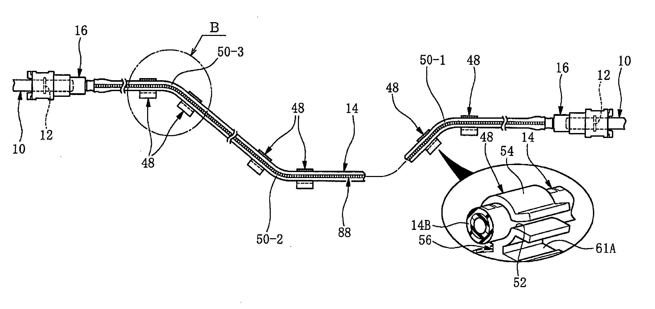
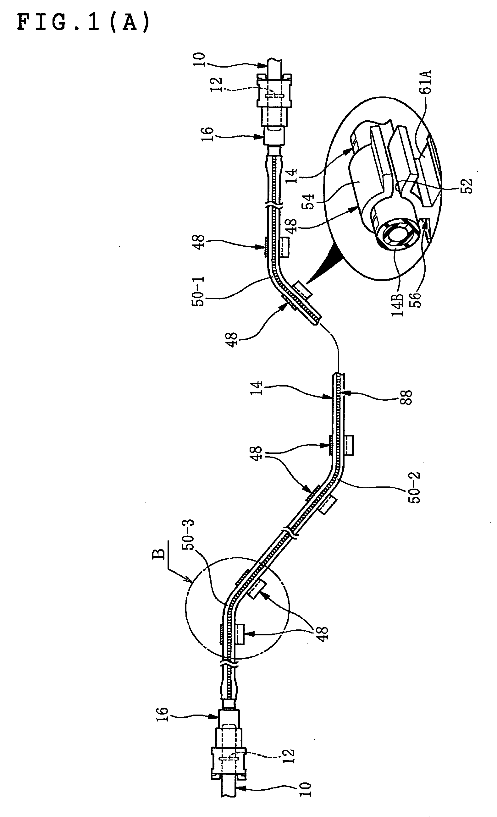
[0140] With reference to FIGS. 2 and 3, reference numeral 10 is a mating pipe that is formed integrally to a component such as an engine or a fuel tank securely fixed to a motor vehicle body. The mating pipe 10 is formed with an engaging projection (pipe-side engaging portion) 12 projecting annularly on and around an outer peripheral surface thereof.

[0141]FIG. 4 shows a resin tube equipped with a connector to be arranged between an engine and a fuel tank in a state before assembled in the motor vehicle body. In Figures, reference numeral 14 indicates the resin tube, reference numeral 16 indicates the connector (quick connector). The connectors 16, 16 are attached to both end portions of the resin tube 14. However, when the resin tube 14 is connected directly to a mating member such as the mating pipe 10 on one end portion of the resin tube by force-fitting or the like, the connector 16 is attached only to the other end portion of the resin tube 14.

[0142] Here, the resin tube 14 ha...


PUM


Abstract

A piping structure for transporting a fuel arranged between an engine and a fuel tank, is constructed by use of a resin tube that is formed in a straight tubular shape. The resin tube is flexed and bent at one or more points along a longitudinal direction of the resin tube to define one or more bent portions and thereby is provided with a predetermined bent shape. The resin tube is fixed in a motor vehicle body so as to retain the bent portions and thereby assembled in the motor vehicle body.

Description

BACKGROUND OF THE INVENTION [0001] 1. Field of the Invention [0002] The present invention relates to a piping structure for transporting a fuel, a resin tube for transporting a fuel adapted in the piping structure, and a method for producing the resin tube. [0003] 2. Description of the Related Art [0004] Previously, a resin tube is used for transporting a fuel, for example, transporting a fuel in a fuel tank to an engine side. [0005] The resin tube is connected to a mating pipe on a motor vehicle body side to constitute a piping system for transporting a fuel. [0006] Previously, for connecting the resin tube with the mating pipe, a connector (quick connector) that permits simple and quick connection with the mating pipe has been used. [0007] The connector of such type is disclosed, for example, in Patent Document 1 below. FIGS. 12 and 13 show an example of specific construction of the connector. [0008] In FIGS. 12 and 13, reference numeral 200 indicates a resin tube, reference numer...

Claims


Application Information

Patent Timeline
IPC IPC(8): F16L25/00
CPCF02M37/0017F16L3/12F16L3/127F16L11/04F16L33/30F16L37/0987F16L2011/047F16L2201/10
Inventor INOUE, TOMOKISASAGAWA, MASAYUKI
Owner SUMITOMO RIKO CO LTD
Why Eureka
Try Eureka