Vehicle brake control apparatus

a technology for brake control and vehicles, applied in brake systems, brake components, transportation and packaging, etc., can solve the problems of total brake power (the sum of braking forces), insufficient fluid pressure brake power applied to the rear wheels, and liable to be unstable in vehicle running

Inactive Publication Date: 2006-06-22
ADVICS CO LTD
View PDF7 Cites 37 Cited by
  • Summary
  • Abstract
  • Description
  • Claims
  • Application Information

AI Technical Summary

Benefits of technology

[0016] The present invention has been made in order to solve such problems, and in vehicle brake control apparatuses executing regenerative and cooperative brake controls using a fluid pressure braking force and a regenerative braking force together at least in front wheels while performing a front / rear brake power proportioning control for preventing rear wheels from being locked ahead of the front wheels, it is an object of the present invention to provide a vehicle brake control apparatus capable of compensating the shortage of a total braking force that may be generated if additional depression is executed during the front / rear brake power proportioning controlling.
[0023] The vehicle brake control apparatus according to the present invention also executes the front / rear brake power proportion controlling. That is, the apparatus includes the front / rear brake power proportion controlling means for controlling front / rear brake power proportioning which prohibits an increase in brake power applied to rear wheels when the rear wheels are liable to be locked ahead of the front wheels during the operation of the brake operating member by the driver.

Problems solved by technology

On the other hand, during the brake-pedal operation by the driver, if the rear wheels are locked ahead of the front wheels, the vehicle running is liable to be unstable.
Thereby, after the additional depression, the fluid pressure brake power applied to the rear wheels is insufficient in comparison with the case where the front / rear brake power proportioning control is not executed (the case where the front / rear brake power proportioning control is executed and the brake-pedal operation demands the same brake power as that after the additional depression).
In other words, the total brake power (the sum of the braking forces applied to front wheels and the braking force applied to rear wheels) after the additional depression is insufficient in comparison with the case where the front / rear brake power proportioning control is not executed.
Accordingly, in this case, characteristics of the total braking force relative to the brake-pedal depressing force is insufficient for predetermined target characteristics, so that the optimum braking force relative to the brake-pedal depressing force cannot be maintained.

Method used


Image

  • Vehicle brake control apparatus
  • Vehicle brake control apparatus
  • Vehicle brake control apparatus

Examples


first embodiment

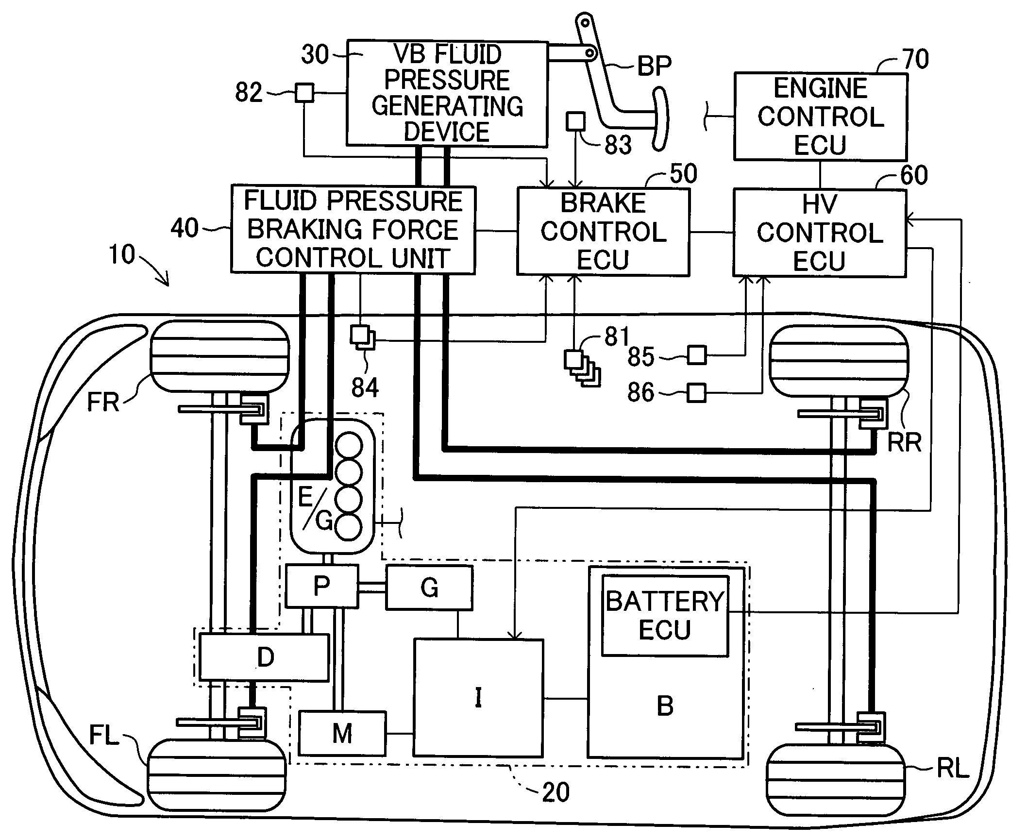
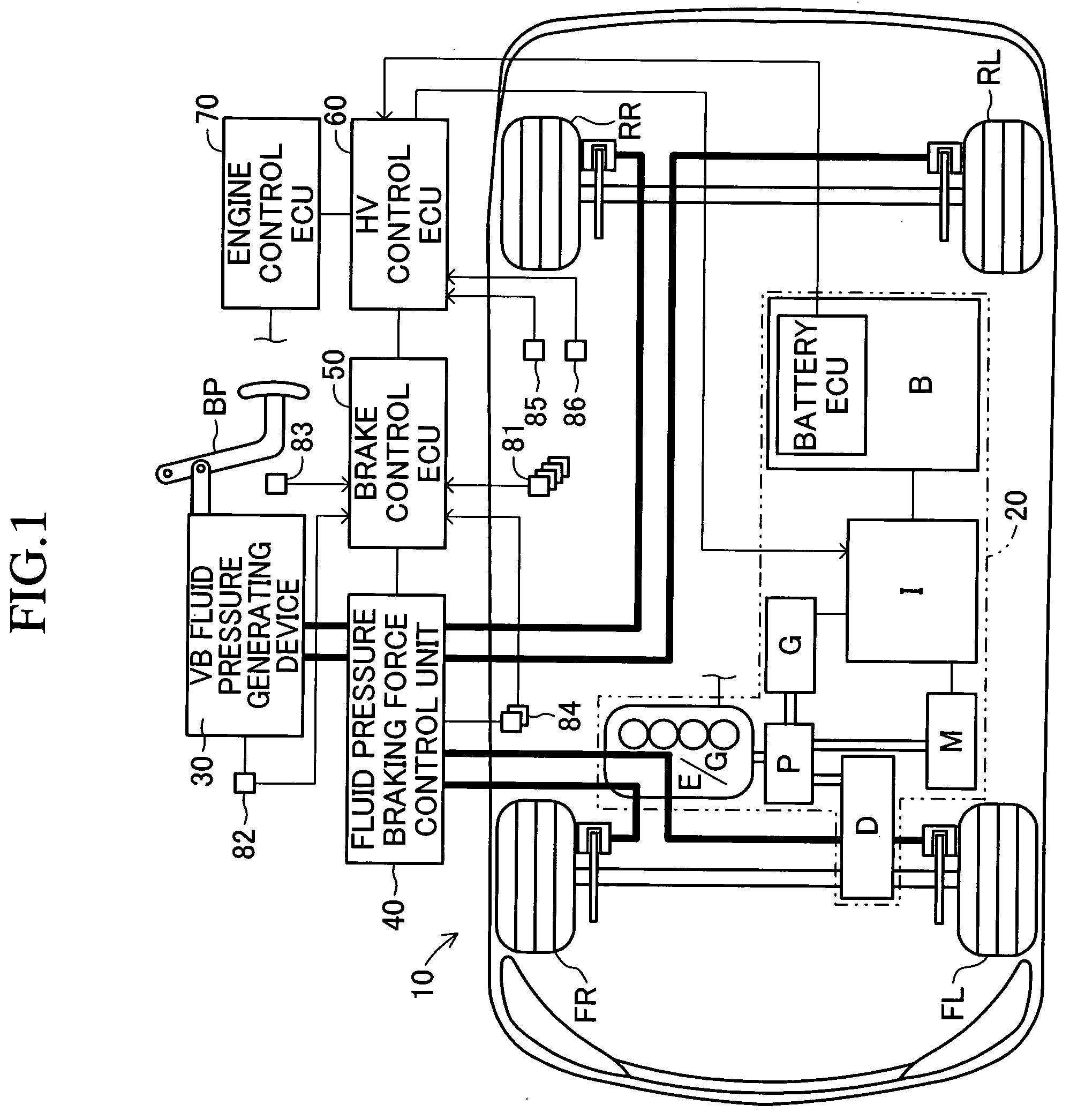
[0063]FIG. 1 is a schematic view of a vehicle having a vehicle brake apparatus 10 according to a first embodiment of the present invention mounted thereon. This vehicle, including two brake fluid pressure circuit lines (i.e., so-called front / rear piping) composed of a line for two front wheels and a line for two rear wheels, is a front-wheel drive hybrid vehicle using an engine and a motor together as a power source for driving the front wheels.

[0064] The vehicle brake apparatus 10 includes a hybrid system 20 having two kinds of drive source, an engine E / G and a motor M, a vacuum booster fluid pressure generating device generating a brake fluid pressure corresponding to the brake-pedal operation by a driver (referred to as a VB fluid pressure generating device 30 below), a fluid pressure braking force control unit 40 for controlling the fluid pressure braking force (specifically, the wheel cylinder fluid pressure) for each wheel, a brake control ECU 50, a hybrid control ECU (referr...

second embodiment

[0187] Next, a vehicle brake apparatus (a vehicle brake control apparatus) according to a second embodiment of the present invention will be described. Principal points in which the second embodiment differs from the first embodiment are that a hydro-booster fluid pressure generating device 30 (referred to as the HB fluid pressure generating device 30 below) is used instead of the VB fluid pressure generating device 30, and the fluid pressure braking force control unit 40 different from that according to the first embodiment is used. In the description of the second embodiment, like reference characters and symbols designate like components and variables common to the first embodiment.

[0188] As shown in FIG. 10, the vehicle brake apparatus according to the second embodiment employs the HB fluid pressure generating device 30 instead of the VB liquid pressure generating device 30 according to the first embodiment. The HB fluid pressure generating device 30, as shown in FIG. 11 illustr...


PUM


Abstract

In a vehicle brake apparatus, front-wheel brake power is controlled with fluid pressure brake power (a front-wheel VB fluid pressure part Fvbf+an increase in fluid pressure brake power equivalent to a liner valve pressure difference ΔP1) and regenerative brake power Freg, while rear-wheel brake power is controlled with only fluid pressure brake power (a rear-wheel VB fluid pressure part Fvbr+an increase in fluid pressure brake power equivalent to a liner valve pressure difference ΔP2), so that regenerative and cooperative brake controlling is executed. When a brake pedal is additionally depressed during front / rear brake power proportion controlling, the shortage of the total brake power is compensated by adding additional brake power Fadd, which is the same as rear-wheel brake power shortage ΔFr generated by the additional depression, to the front-wheel brake power.

Description

BACKGROUND OF THE INVENTION [0001] 1. Field of the Invention [0002] The present invention relates to a brake control apparatus for vehicles. [0003] 2. Description of the Related Art [0004] An automatic braking apparatus for automatically controlling the fluid pressure of wheel cylinders independently of the operation of brake operation members, such as a brake pedal, by a driver has been widely known. For example, the automatic braking apparatus disclosed in Japanese Unexamined Patent Application Publication No. 2004-9914 includes a master cylinder for generating a master fluid pressure (master cylinder fluid pressure and vacuum booster fluid pressure) independently of the operation of a brake pedal on the basis of the operation of a vacuum booster corresponding to the operation of the brake pedal, a fluid pressure pump for generating a pressurizing fluid pressure higher than the master fluid pressure, and a normally open linear electromagnetic valve for adjusting the applied pressu...

Claims


Application Information

Patent Timeline
Patent Type & Authority Applications(United States)
IPC IPC(8): B60T8/64B60K6/445B60L7/24B60L50/16B60T8/17B60T8/1766B60T8/26B60W10/08B60W10/18B60W20/00
CPCB60K6/445B60L7/26B60L2210/20B60T8/1766B60T8/3655B60T8/4872B60T13/586B60T2270/608B60W10/08B60W10/184B60W20/00B60W30/18127Y02T10/725Y02T10/6239Y02T10/62Y02T10/72B60W10/18B60W20/13B60W2710/18
Inventor MATSUURA, MASAHIROSAITO, SHIGERUKOKUBO, KOICHISENGOKU, YUJI
Owner ADVICS CO LTD
Why Eureka
Try Eureka