Rotor for an electrical motor

a technology for electrical motors and rotors, which is applied in the direction of synchronous motors, dynamo-electric machines, magnetic circuit shapes/forms/construction, etc., can solve the problems of increasing the complexity and cost of rotor manufacturing, inappropriate start-up characteristics of synchronous motors, etc., to facilitate the manufacturing process, simplify the design, and facilitate the manufacture of cheaper and more reliable motors.

Inactive Publication Date: 2006-06-22
DANFOSS COMPRESSORS +1
View PDF23 Cites 14 Cited by
  • Summary
  • Abstract
  • Description
  • Claims
  • Application Information

AI Technical Summary

Benefits of technology

[0005] It is an object of the invention to simplify the manufacturing process. In accordance with this object, the invention provides a rotor of the kind which is described in the introduction, in which the rivet means forms part of at least one of the short circuit rings. Due to the reduction of the number of components in the construction, a simpler design and potentially a cheaper and more reliable motor is facilitated.
[0007] The rivet means forms an integrated part of at least one of the short circuit rings and forms a circumferentially extending protrusion of the end face of the rotor. The protrusion may have a shape which matches the shape of the end plate so that the protrusion encircles the end plate when the end plate is positioned on an axial end faces of the core. To fasten the end plate to the end face, the protrusion is deformed, e.g. by use of an embossing tool which is pressed against the protrusion. The Protrusion may e.g. be an annular protrusion. And in order to avoid rotational indexation of the rotor to position an indentation correctly in relation to the protrusion for deforming the protrusion, the annular protrusion may be circular in a cross section perpendicular to the rotational axis of the rotor. In a radial cross section, the protrusion may be triangular so that the protrusion terminates axially outwardly with a relatively sharp tip which facilitates deformation.
[0008] The squirrel cage is made e.g. by arranging the core in a mould of an injection moulding machine in which an electrically conductive material is injected to form not only the substantially longitudinally extending conductors but also the two axially oppositely located short circuit rings and the rivet means in one piece. The squirrel cage can preferably be moulded from aluminium or from an aluminium containing alloy which is electrically conductive and which is preferably soft relative to the magnetically conductive material so that the rivet means is relatively easily deformed when the end plates are attached.
[0009] To lock one end of the cavity for the magnet, an end plate of a first type could be made and attached to a first axial end face of the core during the interlocking process in which the core is made. Subsequently, the squirrel cage could be moulded directly into the slots for the conductors in the core thereby leaving an opening in the second axial end face for insertion of the magnets into the cavity for the magnet after the moulding of the squirrel cage. In that way, the magnets can be protected from the high temperatures generated by the moulding process. Finally, an end plate of a second type may be attached to the second axial face for securing the magnets in the magnet cavities. The end plate of the second type is fastened to the core by deformation of the rivet means so that a part of the rivet means covers the end plate. The end plates of the first and / or the second type is preferably made from a magnetically conductive material, and preferably from the same material as the plates constituting the rotor core. The end plates are provided with apertures with a cross-section at least of the size, or larger than the cross-section of the cavity, or at least of the size, or larger than the cross-section of the opening in the end face into the cavity. The shape of the apertures may, however, be different from the shape of the opening in the end face, or the aperture may be offset with respect to its position over the opening such that a major portion of the opening into the cavity is in communication with the aperture and such that a remaining, minor, portion of the cavity is covered by the end plate to secure the magnet in the cavity. A major portion could be more than 50 pct. such as more than 75 pct. or even such as more than 95 pct. or more than 99 pct. of the cross-sectional area of the aperture is in communication with the opening into the cavity. Preferably, the rotor comprises a plurality of magnets, e.g. arranged symmetrically around a radially extending axis of symmetry, e.g. the axis of rotation of the rotor in the motor. In one embodiment, the aperture is arched, or forms part of a circle extending symmetrically around the centre axis. As an example, a circular aperture could be split into a number of segments separated by bridging portions. In this embodiment, one of the magnets could be secured in the cavity by the inner peripheral edge, and an adjacent magnet could be secured in the cavity by the outer peripheral edge.
[0010] To enable repeated attachment and detachment of the end plate to the rotor core, the end plate may have a peripheral rim with a first rim portion and a second rim portion forming different radial distances to the centre axis. In that way, the end plate could be attached to the end face of the rotor core, e.g. by riveting along the edge, and if the end plate has to be removed, e.g. for replacement of the magnets, the end plate could rotated so that the already existing riveting points do not interfere with the rim portion with the largest radial size of the end plate.

Problems solved by technology

In certain applications, however, the synchronous motor has an inappropriate start-up characteristic.
In any case, the riveting of the end plate increases the complexity and costs of the manufacturing of the rotor.

Method used


Image

  • Rotor for an electrical motor
  • Rotor for an electrical motor
  • Rotor for an electrical motor

Examples


Embodiment Construction

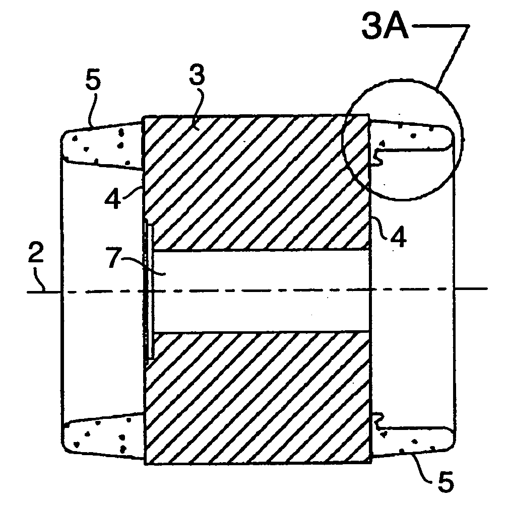
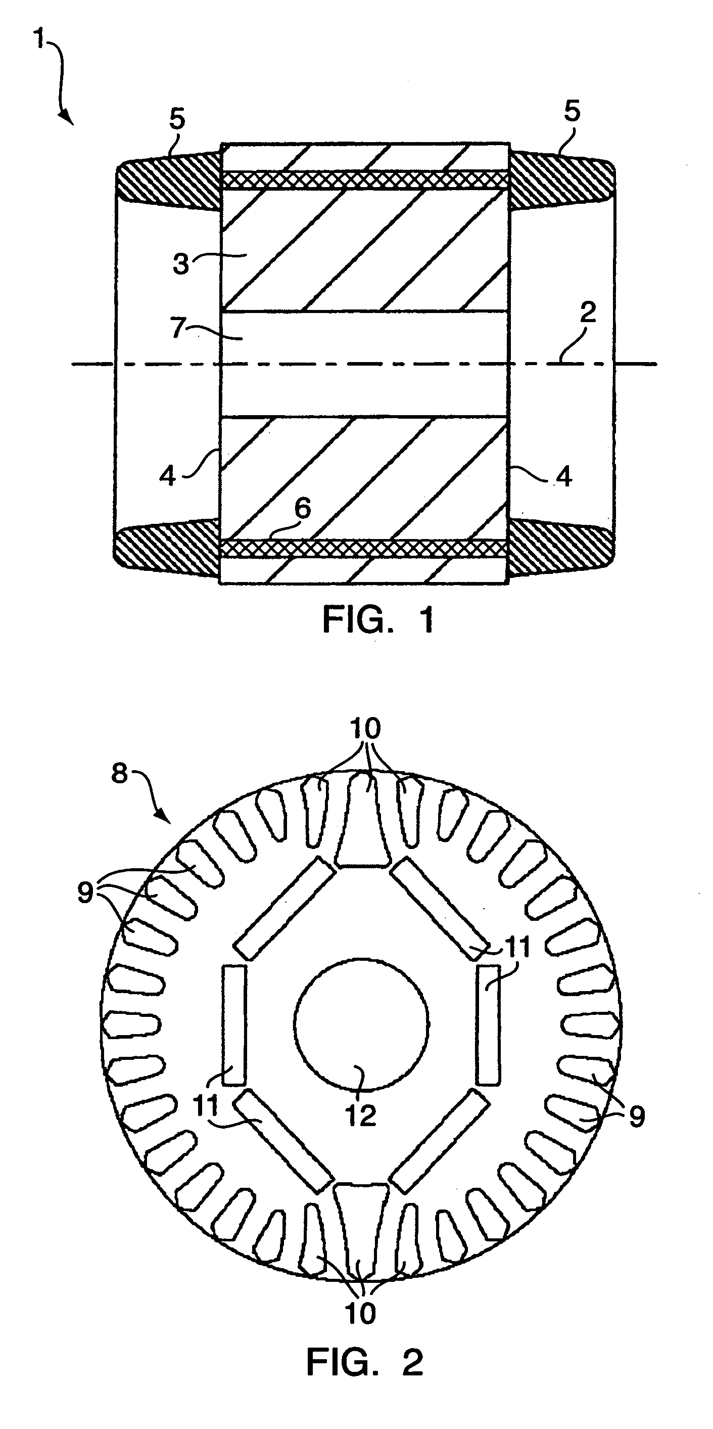
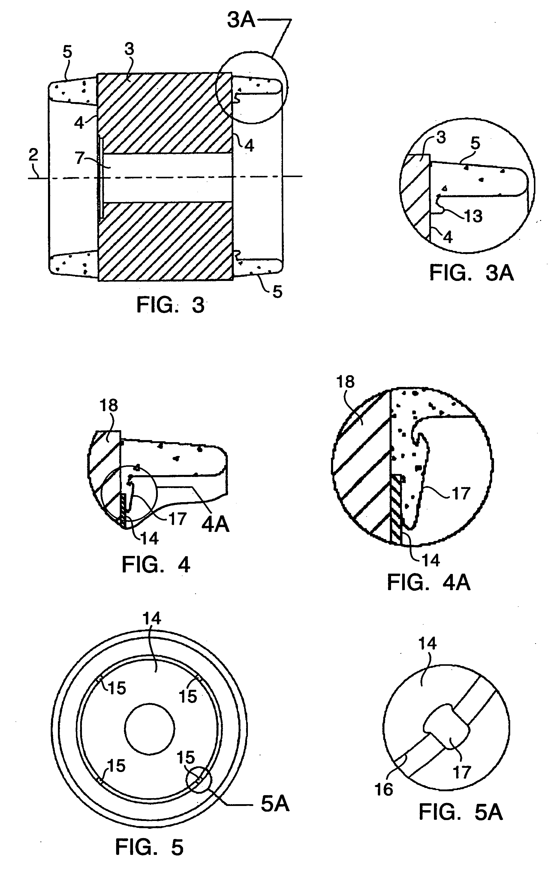
[0023]FIG. 1 shows a rotor 1 which is carried in a stator for rotation around the centre axis 2. The rotor comprises a rotor core 3 with first and second axially opposite end-faces 4. The rotor further comprises first and second axially opposite short circuit rings 5 which join the axially extending windings 6. The rotor is assembled with a drive shaft (not shown) which extends through the opening 7 and which is suspended in rotational bearings to enable rotation of the rotor relative to a corresponding stator (not shown). The rotor is made from sheets of a metal which is stacked to form a laminated core. Each sheet comprises an opening which, in combination with other sheets, forms conductor slots extending axially throughout the rotor. After the assembly of the sheets into a rotor core, conductive bars, constituting the windings, are moulded directly into the conductor slots using the slots as a mould, and the short circuit rings are moulded as an integral part of the bars. To inc...


PUM


Abstract

The invention provides a rotor for an electrical motor. The rotor comprises both a squirrel cage and a number of magnets and can be inserted e.g. in a line-start motor. To secure the magnets in cavities in a core of the rotor, an end plate is attached to one axial end face by rivet means, and to simplify manufacturing of the rotor, the rivet means forms part of at least one of the short circuit rings of the squirrel cage.

Description

CROSS-REFERENCE TO RELATED APPLICATIONS [0001] Applicant hereby claims foreign priority benefits under U.S.C. § 119 from Danish Patent Application No. PA 2004 01957 filed on Dec. 20, 2004, the contents of which are incorporated by reference herein. FIELD OF THE INVENTION [0002] The invention relates to a rotor for an electrical motor, e.g. a line-start motor. The rotor has a core made of a magnetically conductive material and a squirrel cage which is moulded in contact with the core. The squirrel cage comprises axially extending conductors and axially oppositely located short circuit rings moulded from an electrically conductive material. The core comprises, in an axial end face, an opening into a cavity in which a magnet is located. To secure the magnet in the cavity, the rotor comprises an end plate which at least partly covers the end face. The end plate is attached to the core by rivet means. BACKGROUND OF THE INVENTION [0003] In one type of commonly used electrical motors, a st...

Claims


Application Information

Patent Timeline
Patent Type & Authority Applications(United States)
IPC IPC(8): H02K21/12H02K1/06
CPCH02K21/46
Inventor WEIHRAUCH, NIELS CHRISTIANANDERSEN, PETER SCAVENIUS
Owner DANFOSS COMPRESSORS
Why Eureka
Try Eureka