Axial gap permanent magnet reluctance motor and method

a permanent magnet and axial gap technology, applied in the direction of dynamo-electric machines, magnetic circuit rotating parts, magnetic circuit shape/form/construction, etc., can solve the problems of insufficient axial balance, difficult to drive the motor, and machine is not deemed suitable for application, so as to reduce the inertia of the rotor, and enhance the q-axis (torque-producing) flux

Inactive Publication Date: 2006-06-22
UT BATTELLE LLC
View PDF7 Cites 66 Cited by
  • Summary
  • Abstract
  • Description
  • Claims
  • Application Information

AI Technical Summary

Benefits of technology

[0016] A further aspect of the invention is that with stator assemblies on both sides of the rotor, axial loading on the rotor is reduced. In a further aspect, by providing a rotor hub and outer ring of non-magnetic material, a flux return path for flux through the reluctance poles does not pass through supporting parts of the rotor, and the reduction in iron reduces rotor inertia. In still a further aspect, PM covers or outer layers are provided for the PM elements to enhance q-axis (torque-producing) flux through the reluctance poles and to shield the PM elements from harmonics caused by the stator assemblies having a toothed configuration.

Problems solved by technology

Permanent magnet motors produce a back-emf and torque that depend upon the amount of magnetic material; however, after the back-emf reaches the level of the supply voltage it becomes difficult to drive the motor.
Such a machine is not deemed suitable for application as a traction drive motor in an electric or hybrid vehicle.
This does not provide sufficient axial balance under loading conditions encountered by a vehicle traction motor.
The single stator design would result in a heavy axial load under such circumstances.

Method used


Image

  • Axial gap permanent magnet reluctance motor and method
  • Axial gap permanent magnet reluctance motor and method
  • Axial gap permanent magnet reluctance motor and method

Examples


Embodiment Construction

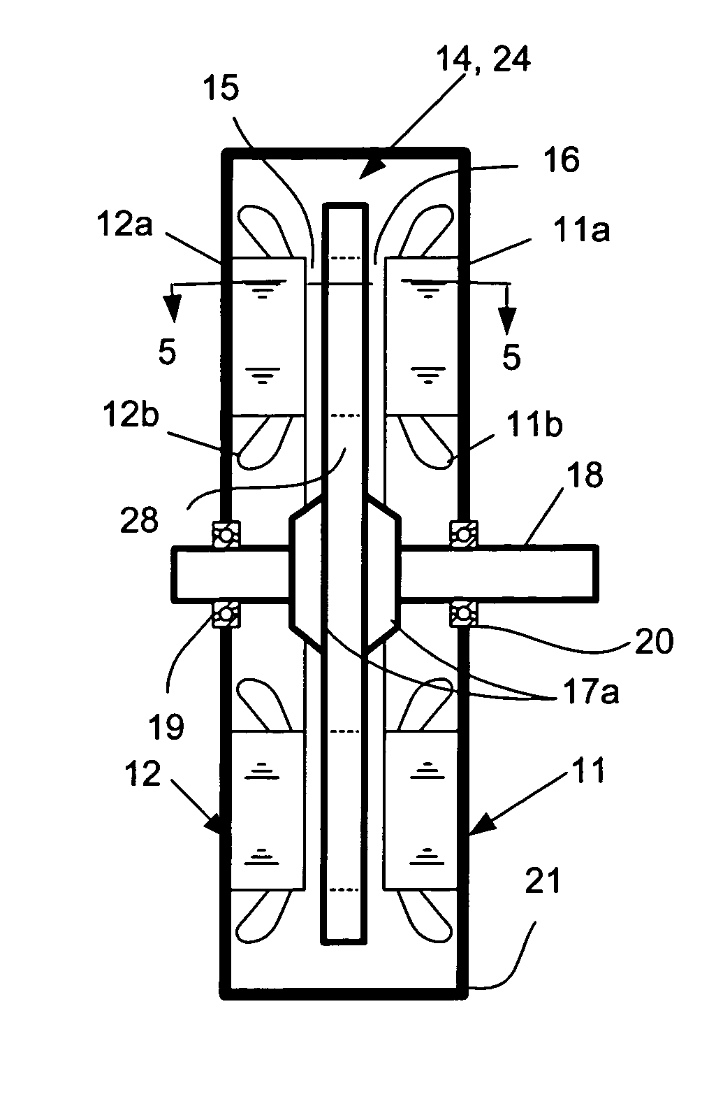
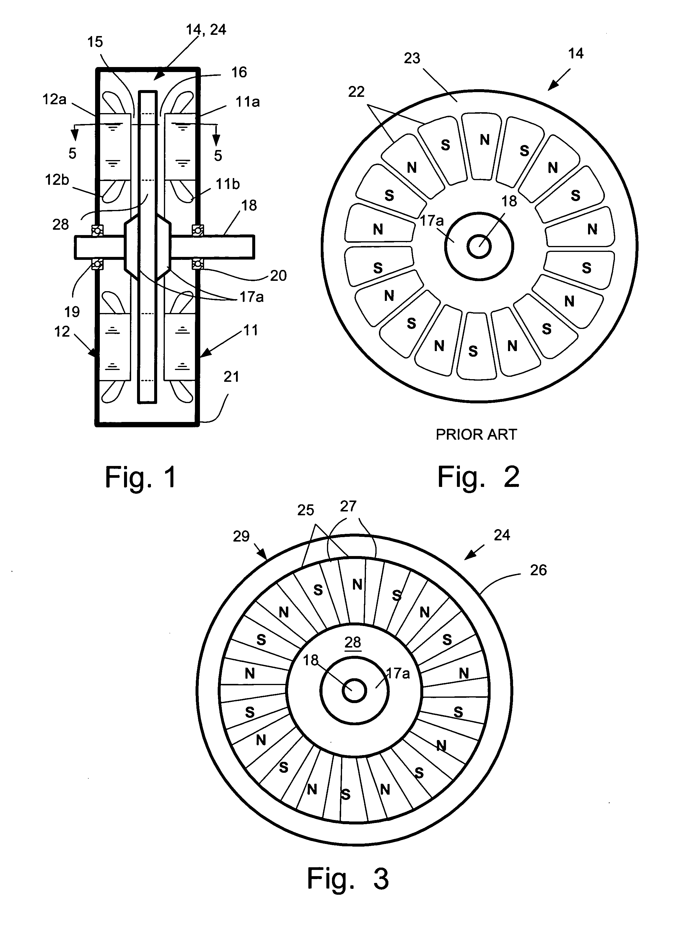
[0033]FIG. 1 is a sectional view of a basic configuration of an axial gap PM machine 10 applicable both to the prior art and to the present invention. FIG. 2 is a plan view of a rotor for the axial machine of the prior art that illustrates portions of permanent magnet (PM) material 22 of north (N) and south (S) polarity embedded in a non-magnetic disk 23 to form a rotor 14. This embodiment provides eighteen such PM poles. A hub 17 is provided and this is securely attached the rotor shaft 18 with the aid of collar pieces 17a seen in FIG. 1. The rotor shaft 18 is carried in bearings 19, 20 in a machine housing 21. The rotor 14 is positioned between two stator assemblies 11, 12 which are spaced apart to provide a vertical operating space for the rotor 14. Each stator assembly includes a core 11a, 12a and a winding of multiple turns of wire 11b, 12b. When the rotor 14 is positioned in that space, two axial air gaps 15, 16 are provided, one between each face of the rotor 14 and a respect...


PUM


Abstract

An electric machine (10) has a disk-shaped rotor (24) disposed in an operating space between two opposing stator assemblies (11, 12) to provide two axial air gaps (15, 16). The rotor (24) has a hub (28) and an outer ring (26) of non-magnetic material and is further provided with a plurality of permanent magnetic elements (25) for coupling flux that is induced by the magnetic field of the stator assemblies (11, 12). The permanent magnetic elements (25) are spaced apart and reluctance poles (27) are positioned in spaces between the magnetic elements (25) to couple additional flux induced by the magnetic field of the stator assemblies (11, 12). Various constructions and shapes (40-45) for the PM magnetic elements (25) are disclosed, and including PM covers (60) of ferromagnetic material for enhancing q-axis flux in the air gaps (15, 16) and for reducing harmonics where toothed stators are used. Methods of providing increased torque using the the various rotor constructions are also disclosed.

Description

CROSS-REFERENCE TO RELATED APPLICATION [0001] This is a continuation-in-part of U.S. patent application Ser. No. 10 / 018,751, filed Dec. 21, 2004, and now copending.STATEMENT REGARDING FEDERALLY SPONSORED RESEARCH [0002] This invention was made with Government support under Contract No. DE-AC05-00OR22725 awarded to UT-Battelle, LLC, by the U.S. Department of Energy. The Government has certain rights in this invention.TECHNICAL FIELD [0003] The field of the invention is brushless machines, including both ac and dc machines, including both motors and generators, and including induction machines, permanent magnet (PM) machines and switched reluctance machines. DESCRIPTION OF THE BACKGROUND ART [0004] There are various radial-gap PM-reluctance motors available in the market. However, there is no axial-gap PM reluctance motor seen in the market. The rotor structure of an axial-gap motor is a thin disk, which is very different from the rotor of the radial-gap motor. [0005] It is commonly k...

Claims


Application Information

Patent Timeline
Patent Type & Authority Applications(United States)
IPC IPC(8): H02K1/22
CPCH02K19/103H02K21/24
Inventor HSU, JOHN S.MCKEEVER, JOHN W.
Owner UT BATTELLE LLC
Why Eureka
Try Eureka