
Electromagnetic wave analysis apparatus and design support apparatus

a technology of electromagnetic wave analysis and design support, which is applied in the direction of instruments, antenna radiation diagrams, measurement devices, etc., can solve the problems of significant electromagnetic interference, enormous amount of time and manpower required to deal with emi, and malfunction of electronic equipmen

Inactive Publication Date: 2006-06-22
PANASONIC CORP
View PDF7 Cites 29 Cited by
  • Summary
  • Abstract
  • Description
  • Claims
  • Application Information

AI Technical Summary

Benefits of technology

[0010] Therefore, with the foregoing in mind, it is an object of the present invention to provide an electromagnetic wave analysis apparatus, a design support apparatus, an electromagnetic wave analysis program, or a design support program that can obtain information about the effect of unwanted radiation noise of electronic equipment on the transmission and reception functions of the electronic equipment.
[0013] Moreover, the correlation value distribution can be provided by an apparatus with a simple configuration that includes the antenna electromagnetic field distribution input portion, the board near electromagnetic field distribution input portion, and the correlation value generator. Thus, it is easy to obtain information about the effect of unwanted radiation noise on the transmission and reception functions of the electronic equipment.
[0015] Accordingly, the present invention can provide an electromagnetic wave analysis apparatus, a design support apparatus, an electromagnetic wave analysis program, or a design support program that can obtain information about the effect of unwanted radiation noise of electronic equipment on the transmission and reception functions of the electronic equipment.

Problems solved by technology

Thus, electromagnetic waves radiated from the printed circuit board, i.e., unwanted radiation noise may cause significant electromagnetic interference (EMI), including a transmission / reception disturbance and malfunction of the electronic equipment.
An enormous amount of time and manpower is required to deal with the EMI.
Because of such a high-speed operating frequency of the IC mounted on the circuit board, the effect of unwanted radiation noise generated from the circuit board on the functions of transmitting and receiving electromagnetic waves of the electronic equipment cannot be ignored.
In other words, they do not propose an apparatus or method for obtaining information about how the unwanted radiation noise will affect the transmission and reception of electromagnetic waves by the electronic equipment.
Therefore, it has been difficult to obtain information about the presence or absence of a transmission / reception disturbance due to the unwanted radiation noise or about a place where the transmission / reception disturbance occurs, e.g., in designing the electronic equipment such as a mobile telephone.

Method used


Image

  • Electromagnetic wave analysis apparatus and design support apparatus
  • Electromagnetic wave analysis apparatus and design support apparatus
  • Electromagnetic wave analysis apparatus and design support apparatus

Examples


embodiment 1

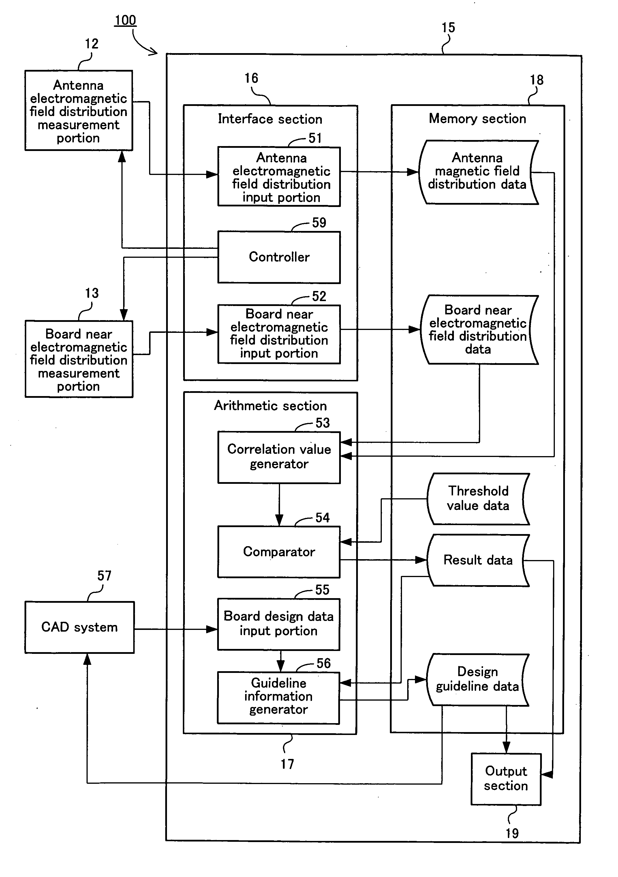
[0106] This embodiment is directed to a design support apparatus that evaluates the transmission and reception characteristics of electronic equipment such as a mobile telephone under conditions close to the actual operation by using two types of distribution data: a board near electromagnetic field distribution of unwanted radiation noise radiated from a printed circuit board of the electronic equipment such as radio equipment including a mobile telephone; and an antenna electromagnetic field distribution for transmission and reception conduced by the mobile telephone.

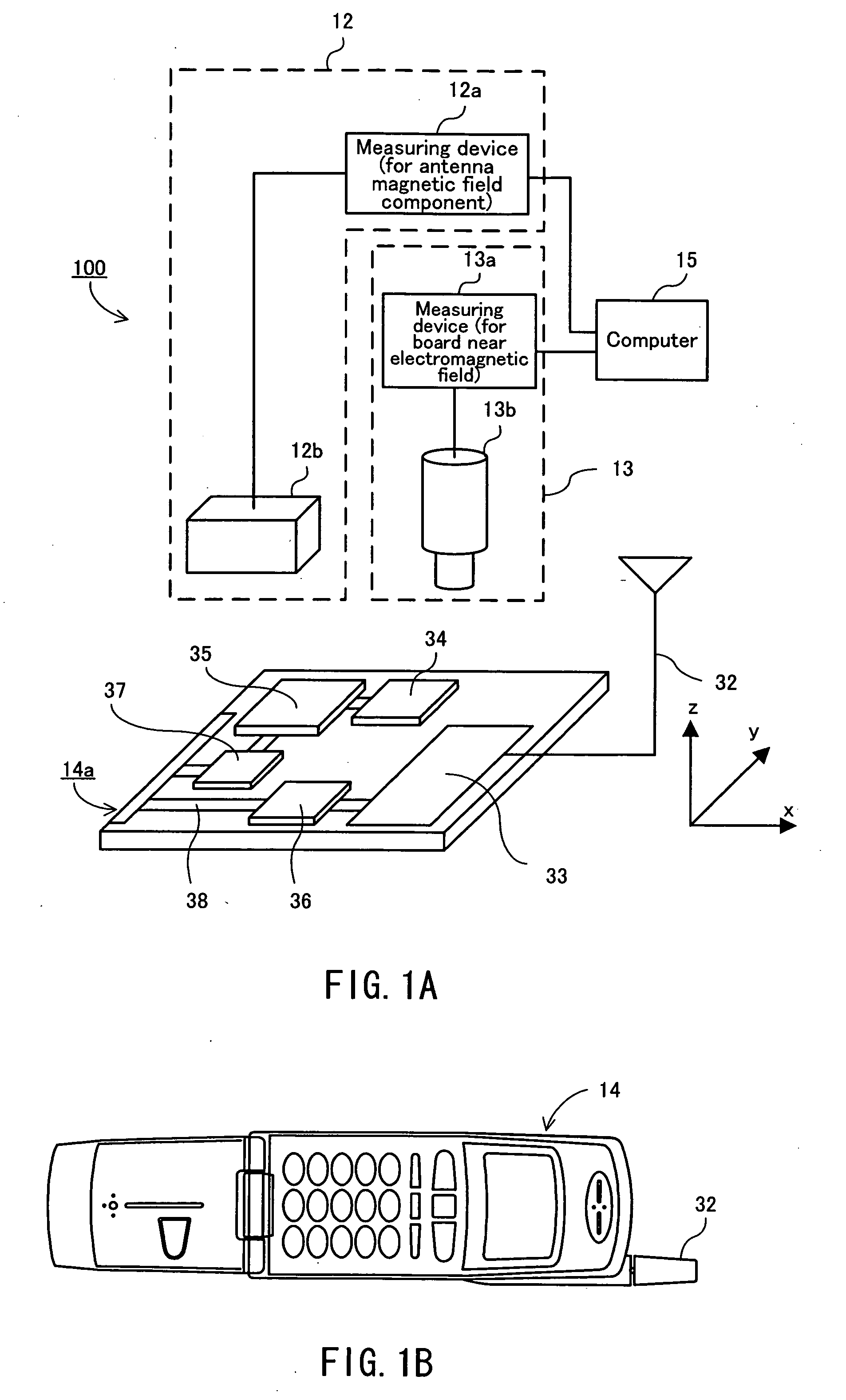
[0107]FIG. 1A is a functional block diagram showing the configuration of a design support apparatus 100 of this embodiment.

[0108] As shown in FIG. 1A, the design support apparatus 100 includes an antenna electromagnetic field distribution measurement portion 12, a board near electromagnetic field distribution measurement portion 13, and a computer 15. The antenna electromagnetic field distribution measurement portio...

example 1

CALCULATION EXAMPLE 1

[0146] A correlation value A (x1, y1, z1) at the position having coordinates (x1, y1, z1) is determined by the following formula 1.

Formula 1

A(x1, y1, z1)=ka2+ma·b+nb2

where k, m and n are constants, a is the intensity of the antenna magnetic field component at the point with coordinates (x1, y1, z1), and b is the intensity of the board near electromagnetic field at the point with coordinates (x1, y1, z1).

[0147] The correlation value A also may be determined by the following formula 2 using a simple calculation.

Formula 2

A(x1, y1, z1)=ma·b

where m is a constant, a is the intensity of the antenna magnetic field component at the point with coordinates (x1, y1, z1), and b is the intensity of the board near electromagnetic field at the point with coordinates (x1, y1, z1).

[0148] It is preferable that the constants such as k, m and n are set appropriately depending on situations while taking into account the relationship with a threshold value (as will be desc...

example 2

CALCULATION EXAMPLE 2

[0149] In the formulas 1 and 2, the correlation value is determined by using the intensity a of the antenna magnetic field component and the intensity b of the board near electromagnetic field. Instead of these scalar values a and b, the antenna magnetic field component and the board near electromagnetic field are expressed as vector values, and the vector values also can be used to determine the correlation value. For example, using a vector a=(ax, ay, az) of the antenna magnetic field component at the point with coordinates (x1, y1, z1) and a vector b=(bx, by, bz) of the board near electromagnetic field at the point with coordinates (x1, y1, z1), the correlation value generator 53 can determine a correlation value A by the following formula 3.

Formula 3

A={(ax·bx)2+(ay·by)2+(az·bz)2}1 / 2

[0150] In the formula 3, the correlation value A is the magnitude of a vector (ax·bx, ay·by, az·bz) whose components are expressed respectively as the products of the x, y and...


PUM


Abstract

A design support apparatus of the present invention includes the following: an antenna electromagnetic field distribution input portion that inputs data indicating an antenna electromagnetic field distribution in the vicinity of electronic equipment; a board near electromagnetic field distribution input portion that inputs data indicating a board near electromagnetic field distribution as unwanted radiation noise radiated from a board of the electronic equipment; and a correlation value generator that generates a distribution of correlation values showing a correlation between the antenna electromagnetic field and the board near electromagnetic field based on the antenna electromagnetic field distribution data and the board near electromagnetic field distribution data.

Description

BACKGROUND OF THE INVENTION [0001] 1. Field of the Invention [0002] The present invention relates to an electromagnetic wave analysis apparatus, a design support apparatus, an electromagnetic wave analysis program, or a design support program that can evaluate the transmission and reception functions of electronic equipment such as a mobile telephone for transmitting and receiving electromagnetic waves. [0003] 2. Description of Related Art [0004] In recent years, electronic equipment as typified by digital audiovisual equipment or a portable information terminal has become smaller and higher performance. As a result of reducing the size and improving the performance, the packaging density of a printed circuit board of the electronic equipment has increased. Moreover, the operating frequency of an integrated circuit (IC) mounted on the printed circuit board is very high. Thus, electromagnetic waves radiated from the printed circuit board, i.e., unwanted radiation noise may cause sign...

Claims


Application Information

Patent Timeline
IPC IPC(8): G01R31/00
CPCG01R29/0814G01R29/0871
Inventor MAEKAWA, TOMOYAOGURA, TETSUYOSHIYAMADA, TORU
Owner PANASONIC CORP
Learn More