
Electronic camera video signal correcting device

a technology of video signal and electronic camera, which is applied in the direction of color television details, television system details, television systems, etc., can solve the problems of large number of dark-time white spots, inability to correctly shoot subjects, and inability to accurately shoot subjects

Inactive Publication Date: 2006-06-22
NIKON CORP
View PDF6 Cites 12 Cited by
  • Summary
  • Abstract
  • Description
  • Claims
  • Application Information

AI Technical Summary

Benefits of technology

[0016] It is an object of the present invention to provide a video signal correcting device of an electronic camera that is capable of obtaining without shooting twice a video signal free from the influence of a dark current and a dark-time white spot by performing dark current correction and dark-time white spot correction.
[0023] According to the aspects of the first to sixth inventions, it becomes possible to correct the dark current and the white spot level according to the temperature, the sensitivity, and the exposure time-in-second by storing plural parameters obtained at the time of dark shooting in the storage unit and using them at the time of shooting a subject.
[0024] Further, according to the aspects of the first to sixth inventions, it is possible to provide a video signal correcting device of an electronic camera that is capable of obtaining without shooting twice a video signal free from the influence of the dark current and the dark-time white spot by performing dark current correction and dark-time white spot correction.

Problems solved by technology

Generally, performing long time-in-second shooting with an electronic camera causes a situation in which a subject cannot be shot correctly due to the influence of dark currents and dark-time white spots.
As a result, it is not possible to correctly shoot a subject.
Furthermore, the higher the sensitivity is, the larger the number of dark-time white spots gets.
Firstly, since dark shooting is performed after normal shooting of a subject is performed for the same length of time-in-second, it takes double the time of the normal shooting to complete shooting.
In particular, when shooting of a celestial photograph etc., for example, requires 10-minute dark shooting after 10-minute normal shooting, and therefore it takes a long time (20 minutes or longer) until the shooting result can be visually recognized on a liquid crystal monitor.
Secondly, shooting twice doubles the power consumption.

Method used


Image

  • Electronic camera video signal correcting device
  • Electronic camera video signal correcting device
  • Electronic camera video signal correcting device

Examples


first embodiment

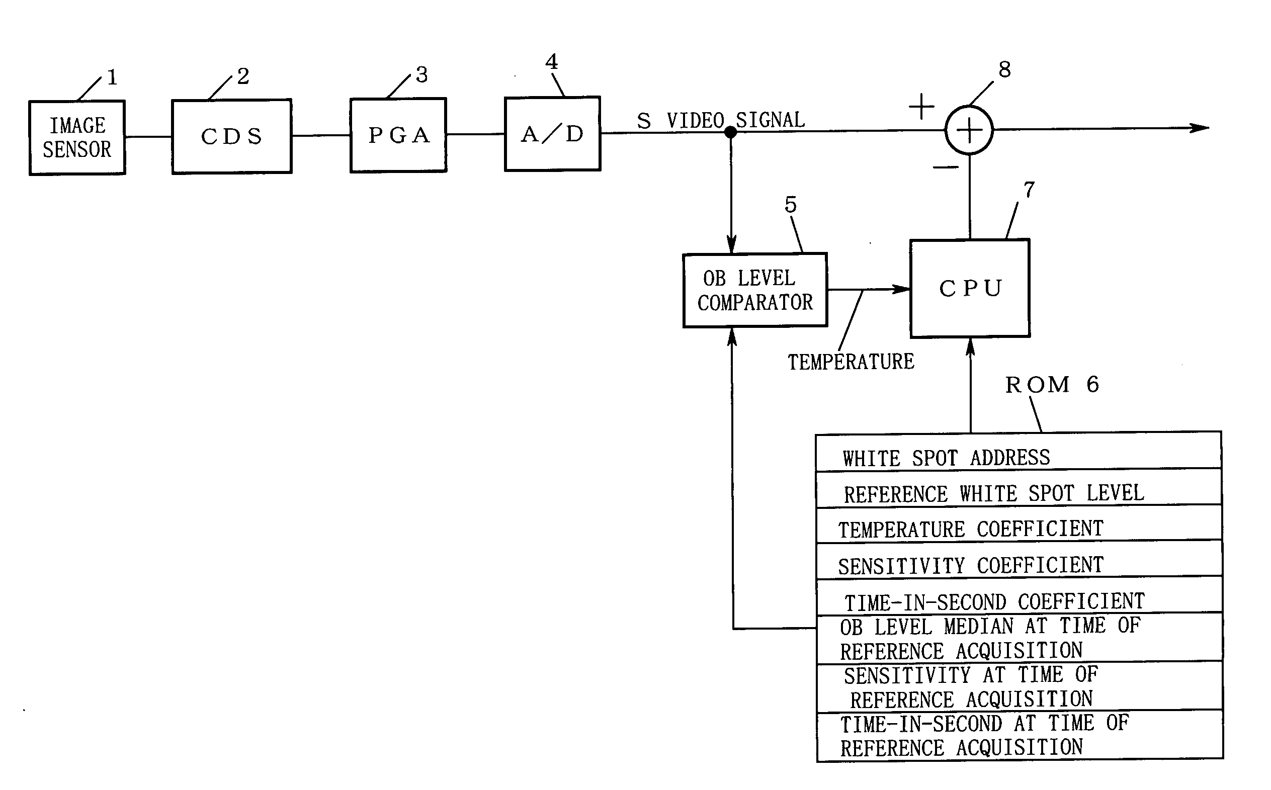
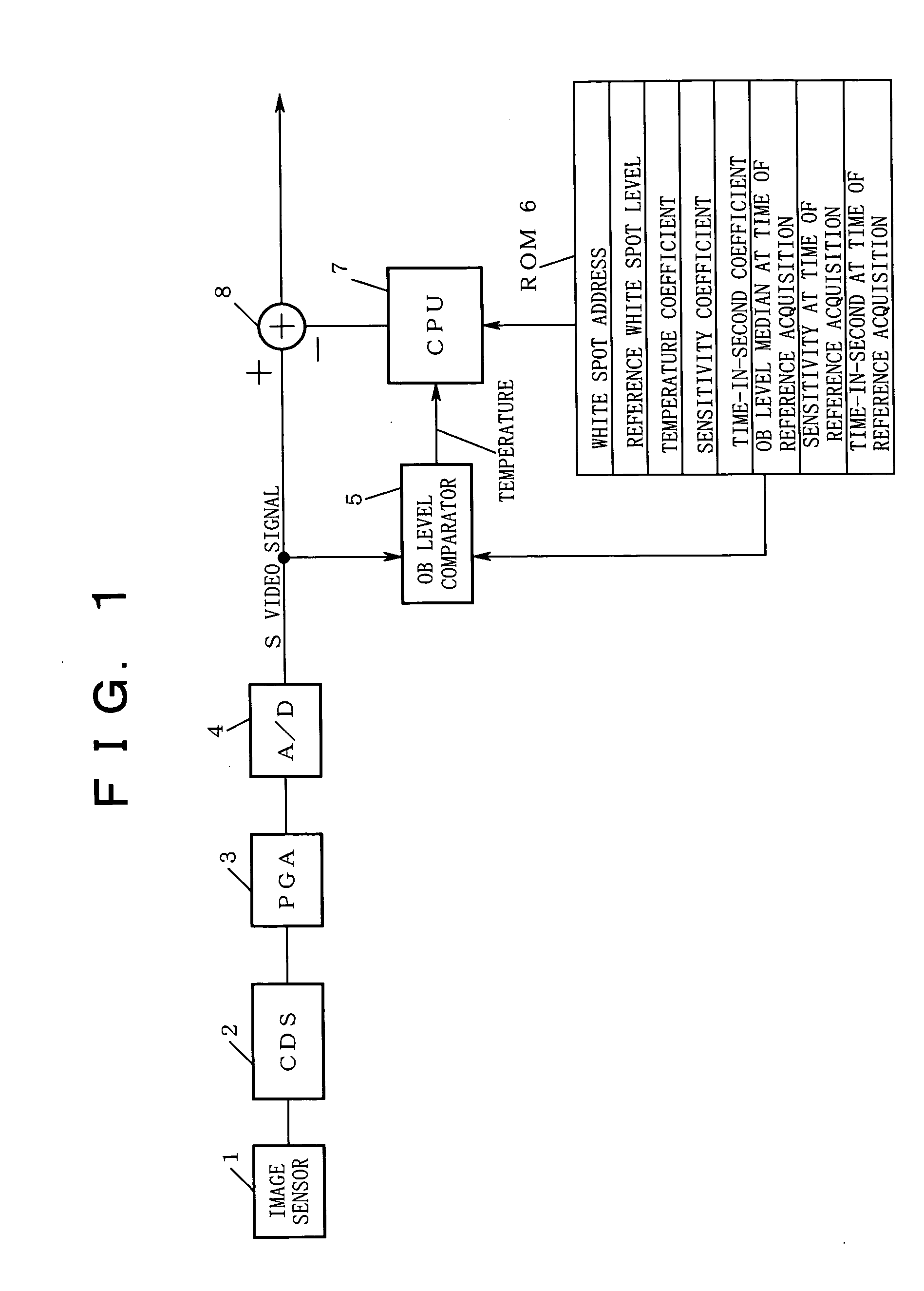
[0030]FIG. 1 is a block diagram showing a first embodiment of the present invention.

[0031] In FIG. 1, reference numeral 1 denotes an image sensor composed of, although not shown in the drawing, plural photodiodes, and CCDs in plural lines for transferring charges generated in each photodiode, etc. Reference numeral 2; a correlated double sampling (referred to as CDS in the figure) circuit, reference numeral 3; a programmable gain amplifier (referred to as PGA in the figure), reference numeral 4; an analog-to-digital converter (referred to as A / D in the figure), reference numeral 5; an optical black level comparator (referred to as OB level comparator in the figure), reference numeral 6; a ROM for storing various data, reference numeral 7; a CPU, and reference numeral 8; an adder.

[0032] Here, the image sensor 1 shoots a subject and outputs a shooting result as an electric signal. As well known, the correlated double sampling circuit 2 has a role to reduce low frequency noise from t...

second embodiment

[0067]FIG. 4 is a block diagram showing a second embodiment of the present invention. In the second embodiment shown in FIG. 4, the same parts as those in the first embodiment shown in FIG. 1 are assigned with the same symbols and the explanation thereof will be omitted.

[0068] The second embodiment differs from the first embodiment in that a temperature sensor 9 is provided instead of the OB level comparator 5 in the first embodiment, the reference dark current level median and the temperature at the time of acquisition of the reference are stored in the ROM 6, and the OB level median at the time of acquisition of the reference is not stored in the ROM 6.

[0069] Additionally, instead of the reference dark current level median, the reference dark current level average may be stored.

[0070] The operation in the second embodiment shown in FIG. 4 will be explained below.

[0071] (1) First, the electronic camera performs dark shooting and stores various data shown in the drawing in the R...


PUM


Abstract

A device stores in ROM white spot addresses, white spot levels, an OB level median, sensitivity, and time-in-second under dark shooting, a temperature coefficient correcting the white spot level according to the temperature under normal shooting, a sensitivity coefficient for the sensitivity-based correction, and a time-in-second coefficient for the exposure time-in-second-based correction. A temperature difference during shooting a subject is obtained according to the difference between OB level median during normal shooting and that during dark shooting. A correction value for the white spot level due to temperature is obtained from temperature difference and temperature coefficient, and similarly, correction value due to sensitivity is obtained from sensitivity difference and sensitivity coefficient, and correction value due to time-in-second is obtained from time-in-second difference and time-in-second coefficient for correction. Dark current is corrected by subtracting OB level median during shooting a subject from the video signal during shooting a subject.

Description

CROSS REFERENCE TO RELATED APPLICATION [0001] This application is a continuation of PCT International Patent Application No. PCT / JP2004 / 009570, filed on Jun. 30, 2004, designating the U.S., and claims the benefit of priority from Japanese Patent Application No. 2003-189509, filed on Jul. 1, 2003, the entire contents of which are incorporated herein by reference.BACKGROUND OF THE INVENTION [0002] 1. Field of the Invention [0003] The present invention relates to a video signal correcting device of an electronic camera suitable for correcting a dark current and a dark-time white spot included in a video signal of an electronic camera. [0004] 2. Description of the Related Art [0005] Generally, performing long time-in-second shooting with an electronic camera causes a situation in which a subject cannot be shot correctly due to the influence of dark currents and dark-time white spots. In other words, a video signal output from an image sensor of an electronic camera generally contains da...

Claims


Application Information

Patent Timeline
Patent Type & Authority Applications(United States)
IPC IPC(8): H04N5/217H04N5/361H04N5/367
CPCH04N5/361H04N5/367H04N25/63H04N25/69H04N25/68
Inventor MORI, YOSHIZO
Owner NIKON CORP
Learn More