Vision inspection apparatus using a full reflection mirror

Active Publication Date: 2006-06-22
MIRTEC
View PDF9 Cites 7 Cited by
  • Summary
  • Abstract
  • Description
  • Claims
  • Application Information

AI Technical Summary

Benefits of technology

[0012] Therefore, a primary object of the present invention to provide a vision inspection apparatus and method using total reflection mirrors capable of expecting an improving effect of inspection operation efficiency as not only a modifyin

Problems solved by technology

However, the prior art vision inspection apparatus and method have problems that each component accompanies large loads on its driving and serious vibrations on its halt since the camera is fixed and the printed circuit board is moved, or the printed circuit board is fixed and the camera is moved for photographing various soldering parts on the printed circuit board, thereby separating the devices from the original position by a vibration of the inspection apparatus itself when the mounted state of the devices is inspected before the soldering process.
Further, a wide installation space is required due to a large-scale of the apparatus itself since a movable space of the camera and the printed circuit board should be occupied.
In addition, the prior art has a problem that an inspection position cannot vis

Method used


Image

  • Vision inspection apparatus using a full reflection mirror
  • Vision inspection apparatus using a full reflection mirror
  • Vision inspection apparatus using a full reflection mirror

Examples


Example

[0029] Hereinafter, the detailed description of a preferred embodiment of the present invention will be apparent in connection with the accompanying drawings.

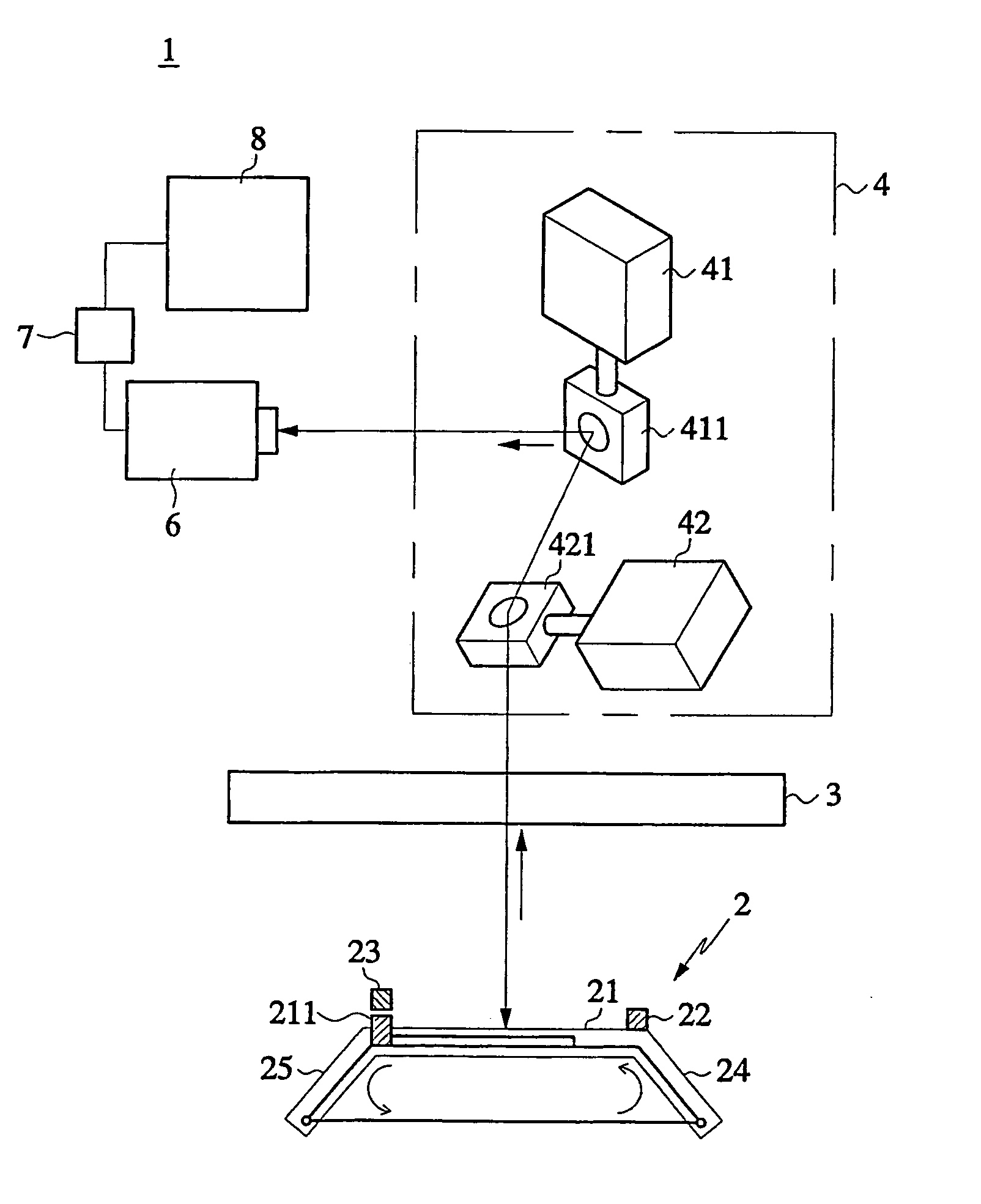
[0030] Referring to FIG. 3A, a vision inspection apparatus 1 in accordance with the present invention is installed so that a printed circuit board that a surface mounting operation is completed in a surface mounting assembly line can accomplish a vision inspection prior to a movement to the next process through a conveyor of a preceding apparatus. As a preferred embodiment, the vision inspection apparatus is installed between a surface mounting machine provided with a conveyor and a re-flow machine or between a high-speed mounting machine and a heteromorphy-mounting machine in the surface mounting assembly line. The vision inspection apparatus in the prior art surface mounting assembly line does not need to change its location as the vision inspection apparatus is located at a dead-space formed between conveyors of the precedi...


PUM


Abstract

The present invention relates to a vision inspection apparatus and method using total reflection mirrors. The present invention provides a vision inspection apparatus using the total reflection mirrors comprising; a board position control module for fixing a printed circuit board; an independent lighting unit for primarily illuminating the printed circuit board; a photographing position control module for changing a reflection angle to required location coordinates of the printed circuit board; a camera for obtaining an image of the printed circuit board; a control unit including a motion controller, a lighting controller, and an to image processor to control the components; and a vision processing unit for reading the image obtained through the camera and judging whether the image is good or bad. The present invention has effects capable of obtaining a clear image of inspection objects by increasing a quantity of light entered into the camera through a stationary direct illuminating type of independent lighting unit, and accomplishing a precise inspection by preventing shadows from generating on the vision inspection of the object such as a printed circuit board on which different sizes of components are mounted.

Description

TECHNICAL FIELD [0001] The present invention relates to a vision inspection apparatus and method using total reflection mirrors. BACKGROUND ART [0002] Generally, a surface mounting technology (SMT) for assembling surface mounting devices (SMD) on a printed circuit board (PCB) etc. comprises a technology of miniaturizing and integrating the surface mounting devices, and technologies of developing precise assembly equipment for assembling the surface mounting devices precisely and operating various kinds of assembly equipments. [0003] In this connection, a surface mounting assembly line is consisted of apparatuses such as a surface mounting machine and a vision inspection apparatus, wherein the surface mounting machine, for mounting the surface mounting devices on the printed circuit board, is supplied various kinds of the surface mounting devices supplied in forms such as tape, stick and tray from a feeder and transfers to a mounting position on the printed circuit board, then, locat...

Claims


Application Information

Patent Timeline
IPC IPC(8): G01N21/00G01N21/956G01R31/309H05K13/04H05K13/08
CPCG01N21/95684G01R31/309H05K13/0413H05K13/08H05K13/0812
Inventor JEONG, JOON-YOUNG
Owner MIRTEC
Why Eureka
Try Eureka