Closure device

a technology of a closure device and a clip, which is applied in the direction of surgical staples, pulse generators, pulse techniques, etc., can solve the problems of time-consuming and expensive procedures, requiring as much as an hour of physician's or nurse's time, and uncomfortable for patients, so as to reduce any tendency to wander and enhance the consistency of clip performan

Inactive Publication Date: 2006-06-22
INTEGRATED VASCULAR SYST
View PDF99 Cites 78 Cited by
  • Summary
  • Abstract
  • Description
  • Claims
  • Application Information

AI Technical Summary

Benefits of technology

[0019] In any event, the primary tines of the clips of the present invention will be offset from the axis of symmetry of the loop from which they extend. The offsetting of the primary tines is achieved by simply relocating the primary tines which are directly attached to the loop to a location which is not on the axis of symmetry of the loop or providing an intermediate connecting element between the tines and the axis of symmetry of the curved region o

Problems solved by technology

This procedure, however, may be time consuming and expensive, requiring as much as an hour of a physician's or nurse's time.
It is also uncomfortable for the patient, and requires that the patient remain immobilized in the operating room, catheter lab, or holding area.
In addition, a risk of hematoma exists from bleeding before hemostasis occurs.
Such devices, however, may be difficult to position properly with respect to the vessel, which may be particularly significant

Method used


Image

  • Closure device
  • Closure device
  • Closure device

Examples


Embodiment Construction

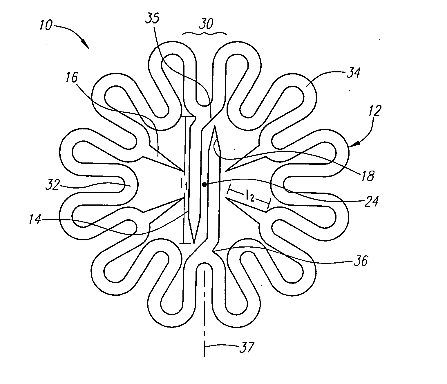
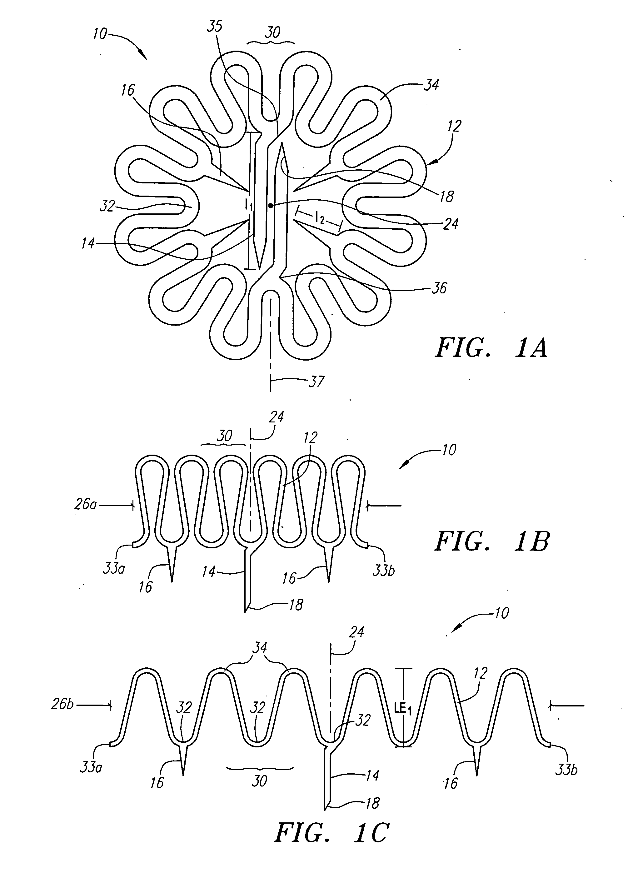
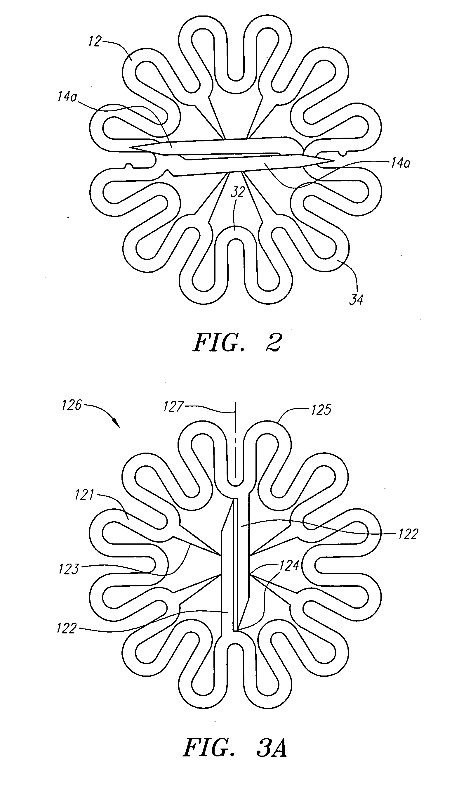
[0033] Turning now to the drawings, FIGS. 1A-1C show a first preferred embodiment of a closure device or clip 10 for closing an incision, puncture, or other passage through tissue, e.g., communicating with a blood vessel or other body lumen (not shown). The clip 10 includes a body 12, which may be generally annular in shape and surrounds a central axis 24, a plurality of primary tines 14 and a plurality of secondary tines 16 extending from the body 12. As used herein, an “annular-shaped body” includes any hollow body, e.g., including one or more structures surrounding an opening, whether the body is substantially flat or has a significant thickness or depth. Thus, although an annular-shaped body may be circular, it may include other noncircular shapes as well, such as elliptical or other shapes that are asymmetrical about a central axis.

[0034] The body 12 includes a plurality of looped or curved elements 30 that are connected to one another to form the body 12. Each looped element ...


PUM


Abstract

A clip for engaging tissue includes a generally annular-shaped body defining a plane and disposed about a central axis extending normal to the plane. The body includes alternating inner and outer curved regions, defining a zigzag pattern about a periphery of the clip. The body is biased towards a planar configuration lying in the plane and deflectable towards a transverse configuration extending out of the plane. Tines extend from the inner curved regions, the tines being oriented towards the central axis in the planar configuration, and parallel to the central axis in the transverse configuration. The tines include primary tines and secondary tines that are shorter than the primary tines. The primary tines may be disposed on opposing inner curved regions and oriented towards one another. The primary tines are configured such that they are offset from the axes of symmetry of the curved regions from which they extend and are connected to the curved regions by curved or linear regions or are connected directly to the curved regions. The primary tines may overlap the body and may be of different lengths.

Description

[0001] This application is a continuation-in-part of U.S. application Ser. No. 10 / 335,075, filed Dec. 31, 2002, which is a continuation-in-part of U.S. patent application Ser. No. 10 / 081,726, now U.S. Pat. No. 6,623,510 and is a continuation-in-part of U.S. patent application Ser. No. 10 / 435,104, filed May 9, 2003, and is a continuation-in-part of U.S. patent application Ser. No. 09 / 732,178, filed Dec. 7, 2000, the disclosures of each of which are incorporated by reference herein.FIELD OF THE INVENTION [0002] The present invention relates generally to apparatus and methods for engaging tissue and / or closing openings through tissue, e.g., into body lumens, and more particularly to devices for closing a puncture in a blood vessel or other body lumen formed during a diagnostic or therapeutic procedure, and to methods for making and using such devices. BACKGROUND [0003] Catheterization and interventional procedures, such as angioplasty or stenting, generally are performed by inserting a...

Claims


Application Information

Patent Timeline
IPC IPC(8): A61B17/08A61B17/00A61B17/064A61B17/068A61B19/00H03K3/356
CPCA61B17/0057A61B17/064A61B17/0644A61B17/068A61B19/54A61B2017/00004A61B2017/00668A61B2017/00867A61B2017/0641A61B90/39
Inventor CARLEY, MICHAEL T.GINN, RICHARD S.SAGASTEGUI, JAVIERSAGASTEGUI, USJABBA, RONALD J.ALDRICH, WILLIAM N.BELEF, W. MARTIN
Owner INTEGRATED VASCULAR SYST
Why Eureka
Try Eureka