Error correction decoding, communication apparatus, and digital transmission system

a technology of error correction and communication apparatus, applied in the field of correlating decoding methods, can solve the problems of increasing the power consumption of the focused node, increasing the interference level at other nodes, and affecting the system due to decoding errors, so as to reduce the interference of the surrounding, efficient information transmission, and efficient data transmission

Inactive Publication Date: 2006-06-29
FUJITSU LTD
View PDF6 Cites 32 Cited by
  • Summary
  • Abstract
  • Description
  • Claims
  • Application Information

AI Technical Summary

Benefits of technology

[0025] In a digital transmission system in which one or more information items decodable by the above-described error correction decoding method are transmitted, the decoding reliability may be transmitted to the node being in communication with the focused communication apparatus. In this case, the counterpart node may control the transmission parameters, such as a coding rate or a transmit power level, in a dynamic manner such that the decoding reliability satisfies a prescribed quality. According to the change in channel communication quality, the minimum coding rate or transmit power level required to achieve a desired decoding reliability can be selected appropriately, and efficient data transmission and reduction of power consumption can be realized. Redundant interference affecting the surroundings can also be reduced by optimizing the transmit power level.
[0026] Thus, by correcting the decoded values based on the decoding reliability in a correlating decoding method, error operations which may arise in the system if using low-reliability decoding results as they are can be prevented.
[0027] By feeding the decoding reliability back to the node being in communication with the focused-on communication apparatus, the coding rate or the transmit power of the counterpart node can be adaptively controlled according to the change in transmission quality. Consequently, efficient information transmission, reduction of power consumption, and reduction of interference level affecting the surroundings can be realized.

Problems solved by technology

However, CQI and TFCI propagate important parameters directed to the essential part of the system performance, and the influence on the system due to decoding error is quite large, as described above.
This may lead to increase of interference level at other nodes and increase of power consumption of the focused node (especially, a waste of battery energy in a mobile phone).
Accordingly, it is an important issue to make further improvement for increasing the system capacity and reducing transmit power levels.

Method used


Image

  • Error correction decoding, communication apparatus, and digital transmission system
  • Error correction decoding, communication apparatus, and digital transmission system
  • Error correction decoding, communication apparatus, and digital transmission system

Examples


first embodiment

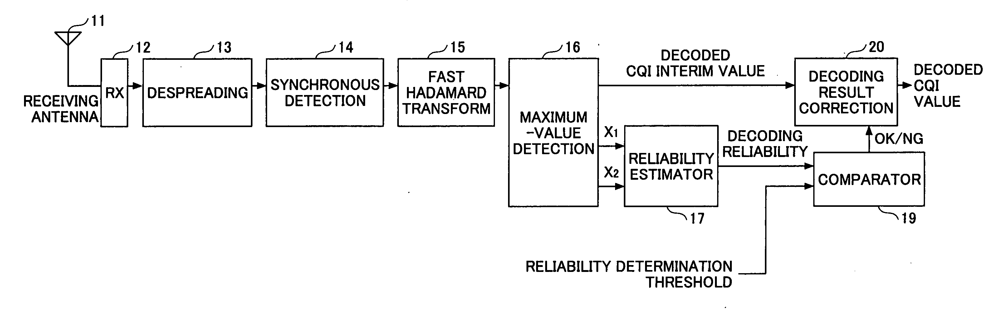
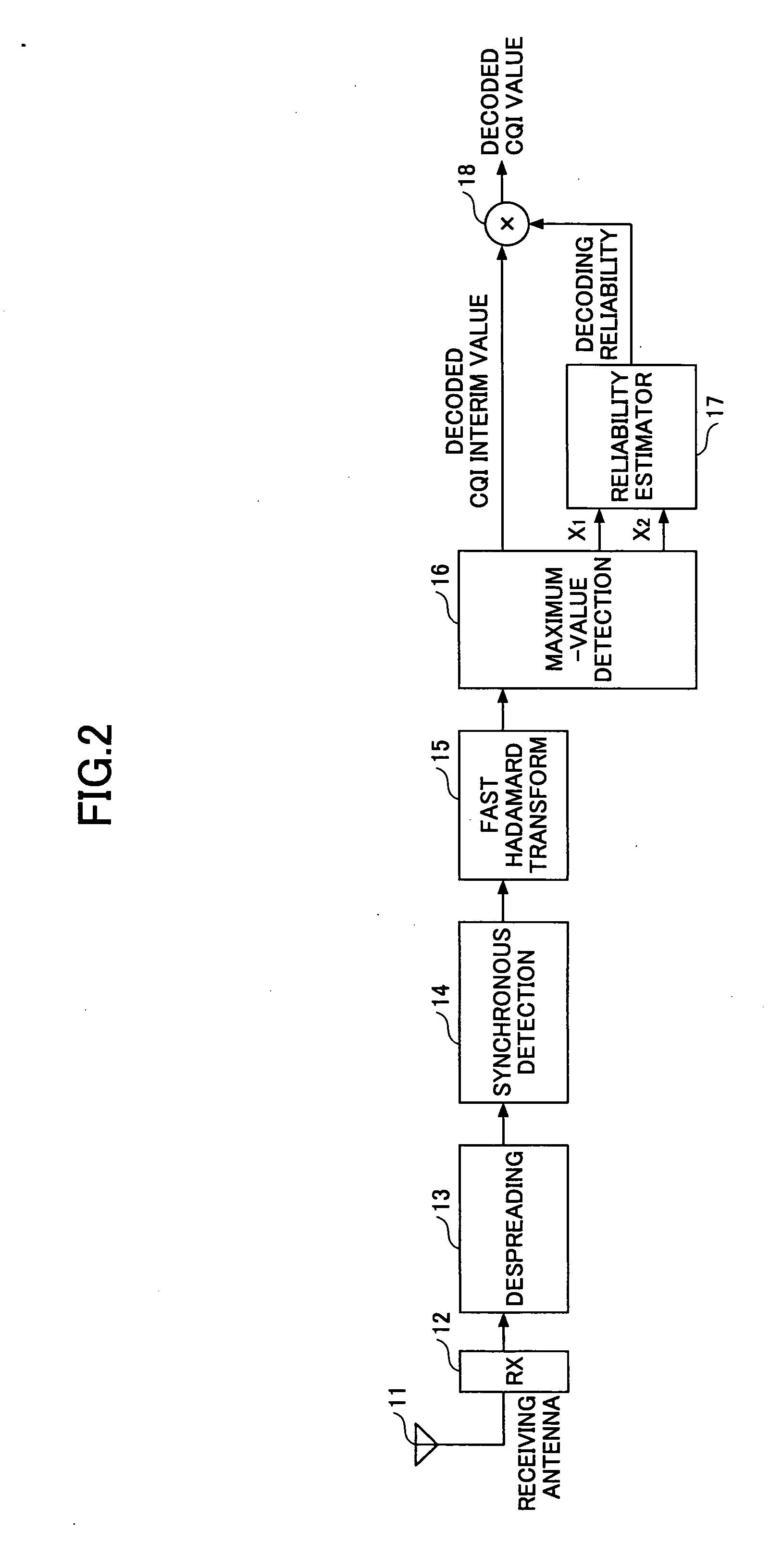
[0040]FIG. 2 is a schematic block diagram illustrating a CQI decoding technique according to the present invention.

[0041] A radio signal received at a receiving antenna 11 is converted to a baseband signal through frequency conversion at an RX unit 12. A despreading unit 13 performs despreading for each user to separate the user signal into physical channels DPCCH, HS-DPCCH, and DPDCH which have been code-multiplexed for each user. The despread symbol of each of the separated physical channels is supplied to the synchronous detector 14, in which phase rotation having occurred in the channel is corrected by channel estimation using the pilot signal mapped on the DPCCH. Since CQI is mapped on the HS-DPCCH, CQI is to be decoded using the synchronous decoding result of the HS-DPCCH. The HS-DPCCH synchronous-detected symbol is input to a fast Hadamard transform (FHT) unit 15, and subjected to correlation with 32 code words.

[0042] In general, the Hadamard transform is expressed as

{right...

third embodiment

[0083]FIG. 9 is a block diagram illustrating a digital (wireless) transmission system according to the invention. This system is on the presumption that at least a portion of information (I) transmitted from a second node (communication apparatus) 200 to a first node (communication apparatus) 100 is encoded using a coding scheme decodable by correlating decoding.

[0084] The first communication apparatus 100 includes a receiver and a transmitter. The receiver includes a receiving antenna 101, an RX unit 102, a demodulator 103, a correlating decoder 104, a reliability estimator 105, and a multiplier 106. The transmitter includes an encoder 107, a frame generator 108, a modulator 109, a TX unit 110, and a transmission antenna 111. The receiver is similar to that of the first embodiment shown in FIG. 2; however, the despreader 13 and the synchronous detector 14 are replaced by the demodulator 103. Accordingly, the structure and the method of the third embodiment can be expanded to genera...

fourth embodiment

[0094] With the digital transmission system of the fourth embodiment, the transmit power is adjusted to a level required at least to maintain the decoding reliability so as to satisfy the required quality in accordance with the channel quality. Consequently, excessive power consumption and interference against the surroundings can be prevented.


PUM


Abstract

An error correction decoding method using a correlating decoding technique is provided. The method includes the steps of estimating a decoding reliability of a decoding result using one or more correlation values acquired in a correlating process; and correcting the decoding result according to the decoding reliability.

Description

BACKGROUND OF THE INVENTION [0001] 1. Field of the Invention [0002] The present invention generally relates to a correlating decoding method using a maximum likelihood (ML) detection algorithm, and more particularly, to an error correction decoding technique for improving decoding characteristics, as well as to a communication apparatus and a digital transmission system using the error correction decoding technique. [0003] 2. Description of the Related Art [0004] W-CDMA (Wideband Code Division Multiple Access) systems, which systems are standardized as the third-generation mobile communications systems, employ a Reed-Muller code for encoding a transport format combination indicator (TFCI) or a channel quality indicator (CQI). See 3GPP TS (3rd Generation Partnership Project Technical Specification) 25.212. [0005] The transport format combination indicator (TFCI) is used to report a combination of transport channels multiplexed on layer 1, such that a communication node that receives ...

Claims


Application Information

Patent Timeline
Patent Type & Authority Applications(United States)
IPC IPC(8): H04L27/06H03M13/45H04B1/707H04L1/00
CPCH04L1/001H04L1/0028H04L1/0033H04L1/0035H04L1/0039H04L1/0054H04L1/0072H04W52/04
Inventor FUTAMI, TETSUHIROKIMURA, DAI
Owner FUJITSU LTD
Why Eureka
Try Eureka