Sensor system, garment and heart rate monitor

sensor system technology, applied in the field of sensor system a garment and a heart rate monitor, can solve the problems of increasing the malfunction making the use of the heart rate monitor more difficult,

Active Publication Date: 2006-06-29
POLAR ELECTRO
View PDF9 Cites 106 Cited by
  • Summary
  • Abstract
  • Description
  • Claims
  • Application Information

AI Technical Summary

Benefits of technology

[0009] The sensor system, garment and heart rate monitor according to the invention provide several advantages. The flexible film structure allows implementing the sensor system such that the pressing sensation placed on the user's body rem

Problems solved by technology

The criteria presented above make the use of the heart rate monitor m

Method used


Image

  • Sensor system, garment and heart rate monitor
  • Sensor system, garment and heart rate monitor
  • Sensor system, garment and heart rate monitor

Examples


Embodiment Construction

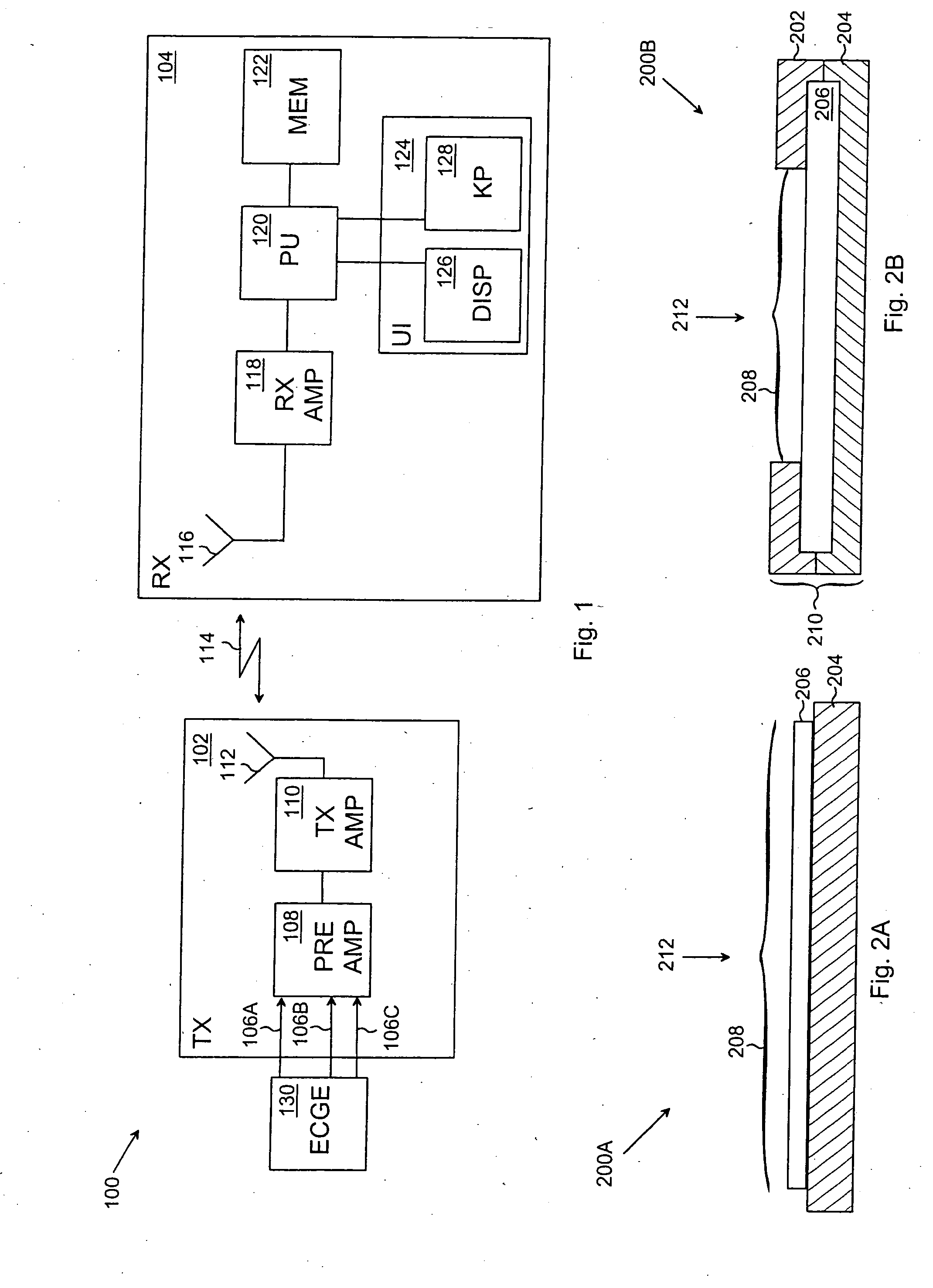
[0024]FIG. 1 shows an example of the structure of a heart rate monitor 100 based on wireless data transmission. The heart rate monitor 100 typically comprises a sensor system 130, an ECG preamplifier 108 (ECG, Electrocardiogram) provided with differential input terminals, a transmitter amplifier (TX AMP) 110, a transmitter antenna 112, a receiver antenna 116, a receiver amplifier (RX AMP) 118, a processing unit (PU) 120, a memory unit (MEM) 122 and a user interface (UI) 124.

[0025] In the example shown in FIG. 1 the heart rate monitor 100 is divided into a transmitter unit 102 and a central processing unit 104 communicating through an electromagnetic field 114. However, the present solution is not restricted to the divided structure shown, instead the heart rate monitor 100 may be composed of a single functional unit, in which the functionalities of the transmitter unit 102 and the central processing unit 104 are combined.

[0026] The sensor system 130 detects the electrocardiogram o...


PUM


Abstract

The invention relates to a sensor system, a garment and a heart rate monitor. The sensor system comprises at least one flexible film structure comprising: a first insulation layer and at least one electric conductor layer formed on top of the first insulation layer and comprising an electrode area, which is configured to establish an electric contact with the surface of the user's skin and to generate as output an electric signal proportional to a momentary value of the electrocardiogram.

Description

FIELD [0001] The invention relates to a sensor system a garment and a heart rate monitor. BACKGROUND [0002] A user-specific portable heart rate monitor typically comprises a transmitter belt to be placed around the user's chest, which transmitter belt indicates an electrocardiogram from the surface of the user's skin and sends the electrocardiogram or a pulse characterizing a part thereof wirelessly to the central processing unit of the heart rate monitor, which typically is a wrist receiver to be placed on the user's wrist. When measuring an electrocardiogram weak voltage levels are determined from the surface of the skin, which requires a high-quality electric contact between the user's skin and the detection electronics of the transmitter belt. An electric contact of high quality typically requires that the transmitter belt is sufficiently tightly placed around the chest, an adequate amount of moisture between the transmitter belt and the skin to provide the tightness and a preci...

Claims


Application Information

Patent Timeline
IPC IPC(8): A61B5/04A61BA61B5/0245A61B5/276
CPCA61B5/0245A61B5/04085A61B5/0424A61B5/6805A61B5/282A61B5/276
Inventor RYTKY, PEKKA
Owner POLAR ELECTRO
Why Eureka
Try Eureka