
Rack and pinion electro-steering

a technology of electro-steering and racks, which is applied in the direction of steering gears, power-driven steering, bearings, etc., can solve the problems of high noise generation, high noise source, and disturbing noise of rack-and-pinion electro-steering systems, so as to prevent dust, minimize noise between thrust members and housing parts surrounding thrust members, and move easily

Inactive Publication Date: 2006-07-06
ROBERT BOSCH AUTOMOTIVE STEERING
View PDF27 Cites 9 Cited by
  • Summary
  • Abstract
  • Description
  • Claims
  • Application Information

AI Technical Summary

Benefits of technology

The present invention provides a rack-and-pinion electro-steering system that addresses disadvantages such as noises and wear of the pinion toothing. The system includes a bearing between the rack and the housing for guiding the rack, preventing tilting of the rack and reducing wear of the pinion toothing. The use of a sliding bearing for guiding the rack and a lock geometry for secure mounting of the sliding bearings on the rack are particularly advantageous for rack-and-pinion electro-steering systems having two pinions engaging into the rack. The thrust member is made of plastic, which minimizes noises and eliminates the need for an O-ring to prevent dust and dirt from entering. The system also simplifies the installation process and reduces the cost compared to existing systems.

Problems solved by technology

The rack-and-pinion electro-steering system can produce disturbing noises.
One source of noise is the rack and another source of noise are the thrust members.
The noise generation is especially high in rack-and-pinion electro-steering systems that have two thrust member / pinion pairings, due to the degrees of freedom at the rack and thrust members.
The disturbing noise generation, however, occurs also in rack-and-pinion electro-steering systems that have merely one thrust member / pinion pairing.
A cause of the noise generation is to be found in that the different toothing forces on the sensor side and servo-side cause a tilting of the rack which results in a knocking of the steering system particularly in rapidly alternating steering.
The tilting of the rack may also result in a high degree of wear of the pinion toothing.
Irrespective of, or in addition to, the noise generation on account of the rack, undesired noises are also generated due to the thrust members, which are embedded in a housing part, having a tendency to tilt.
In conventional systems, the tilting of the rack may result in a high degree of wear, which may be minimized since the bearing prevents a tilting of the rack.

Method used


Image

  • Rack and pinion electro-steering
  • Rack and pinion electro-steering

Examples


Embodiment Construction

[0022] Certain rack-and-pinion electro-steering systems are conventional and are generally used as an alternative to a hydraulic system. Rack-and-pinion electro-steering systems essentially exist as pinion drives, as double pinion drives or as axially parallel drives. Depending on the arrangement, one or two pinions engage in the rack.

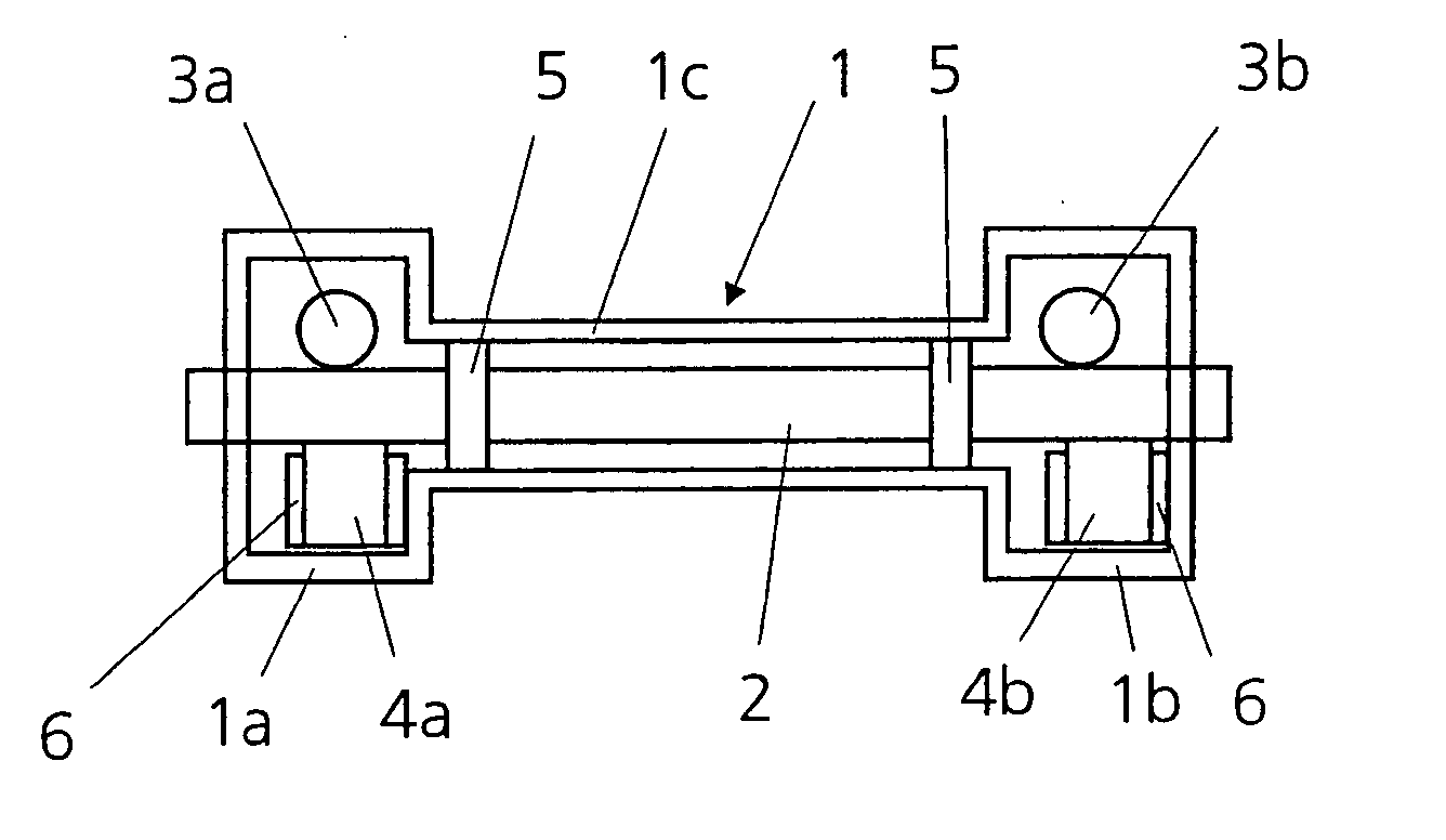
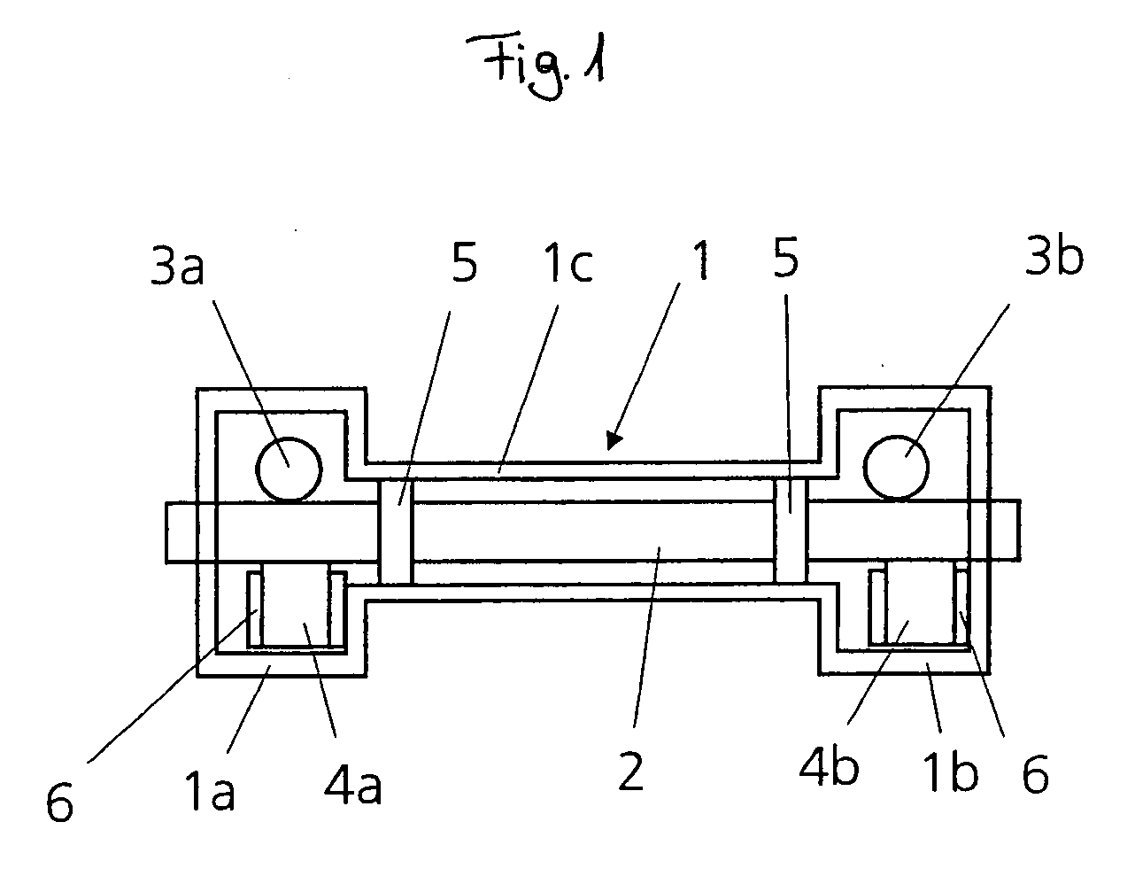
[0023]FIG. 1 illustrates a section of a rack-and-pinion electro-steering system having a housing 1 and a rack 2 extending within it. Rack 2 is operatively connected with two pinions 3a, 3b, each of which includes one thrust member 4a, 4b assigned to it. Pinion 3a is connected in the exemplary embodiment to a servo-side or an electric motor, while pinion 3b is connected to a sensor side or to a steering column.

[0024] Between rack 2 and the cylindrical part 1c of housing 1 surrounding rack 2, two bearings in the form of sliding bearings 5 are arranged. Sliding bearings 5 are used for guiding rack 2 in housing 1, which means that this task no longer has...


PUM


Abstract

A rack-and-pinion electro-steering system, e.g., for motor vehicles, has a rack extending in a housing, which is operatively connected to a thrust member / pinion pairing. At least one bearing between the rack and the housing is provided for guiding the rack. The bearing is arranged as a friction bearing. A construction of the bearing between the rack and the housing as a sliding bearing may be particularly suited for a reliable, durable and cost-effective guidance of the rack in the housing. In addition, for mounting the sliding bearings on the rack, a lock geometry is provided by which the sliding bearings may be locked after having been mounted on the rack. The lock geometry for example may be based on the lock geometry customary in sealing rings in automatic transmissions.

Description

FIELD OF THE INVENTION [0001] The present invention relates to a rack-and-pinion electro-steering system, e.g., for motor vehicles, having a rack extending in a housing, which is operatively connected to a thrust member / pinion pairing. BACKGROUND INFORMATION [0002] Rack-and-pinion electro-steering systems are operated by an electrical system instead of a hydraulic system. It is made up of an electric motor, a gear unit for power transmission as well as the control electronics and sensor system. The steering torque exercised by the driver is evaluated by the sensor system of the power steering and is converted into an electrical signal which is converted by the electric motor and the gear unit into a corresponding servo-torque and transmitted to the steering. Conventional rack-and-pinion electro-steering systems are steering column drives, pinion drives, double pinion drives as well as axially parallel drives. [0003] In conventional rack-and-pinion electro-steering systems, the rack ...

Claims


Application Information

Patent Timeline
Patent Type & Authority Applications(United States)
IPC IPC(8): B62D5/04B62D3/12F16C29/02F16C35/02
CPCB62D3/12B62D3/126F16C29/02F16C35/02
Inventor BEUTLER, OLAFKARCH, CHRISTIANSCHULER, ROBERT
Owner ROBERT BOSCH AUTOMOTIVE STEERING
Learn More