Polymeric solid supports for chromatography nanocolumns

Active Publication Date: 2006-07-06
WATERS TECH CORP
View PDF45 Cites 52 Cited by
  • Summary
  • Abstract
  • Description
  • Claims
  • Application Information

AI Technical Summary

Problems solved by technology

Yet another approach uses screens to provide a containment device that serves as an alternate to frits, but screens generally have a lower limit of performance based on the size of the wire or filament used.
However, screens offer low back pressure compared to frits.
Frits also cause a void volume that reduces the quality of chromatographic data

Method used


Image

  • Polymeric solid supports for chromatography nanocolumns
  • Polymeric solid supports for chromatography nanocolumns
  • Polymeric solid supports for chromatography nanocolumns

Examples


example 1

of Column

[0115] Beds of 3.5 μm Symmetry C18 stationary phase material were chemically immobilized using poly(dimethylsiloxane) (PDMS) as a “nanoglue” to hold the particles together. A New Objective Integra frit column (75 μm fused silica capillary, New Objective, Inc., Woburn, Mass., USA) was packed using a 5 mg / mL of 3.5 μm Symmetry C18 particles (Waters Corporation, Milford, Mass., USA) in acetone. After packing to a bed length of 12 cm, the column was removed and allowed to dry under ambient conditions. The column was then carefully cut into three 4 cm lengths of packed capillary and the Integra frit (New Objective, Inc., Woburn, Mass., USA) was removed from the terminus of the last section. Three solutions of 1%, 5%, and 10% PDMS in 1,4-dioxane were prepared by sequentially adding the monomers of the two component PDMS Sylgard 184 kit (Dow Coming Corporation, Midland, Mich., USA) in a 10:1 monomer A:monomer B ratio. The three sections of packed capillary were then dipped in to o...

example 2

of Column

[0116] An alternative method to that of Example 1 includes a step of immediate sintering of a slurry of Symmetry C18 particles in a 5% PDMS solution, which had been drawn into the capillary. A 20 cm length of 75 μm i.d. fused silica capillary was dipped into a 100 mg / mL slurry of 3.5 μm Symmetry C18 material in 5% PDMS in ethyl acetate for 3 s. During this time 1 cm of the capillary was filled with slurry solution. The 1 cm section of the filled capillary was then placed into the resistive heating coil of an Innovatech frit making device (InnovaTech, Stevenage, Hertfordshire, United Kingdom), which was used to heat the area to about 350° C. Similar results may be achieved with a heated wire cutter or even with a lighted candle.

example 3

of Column

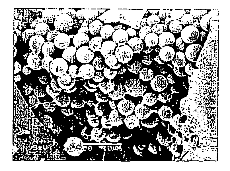
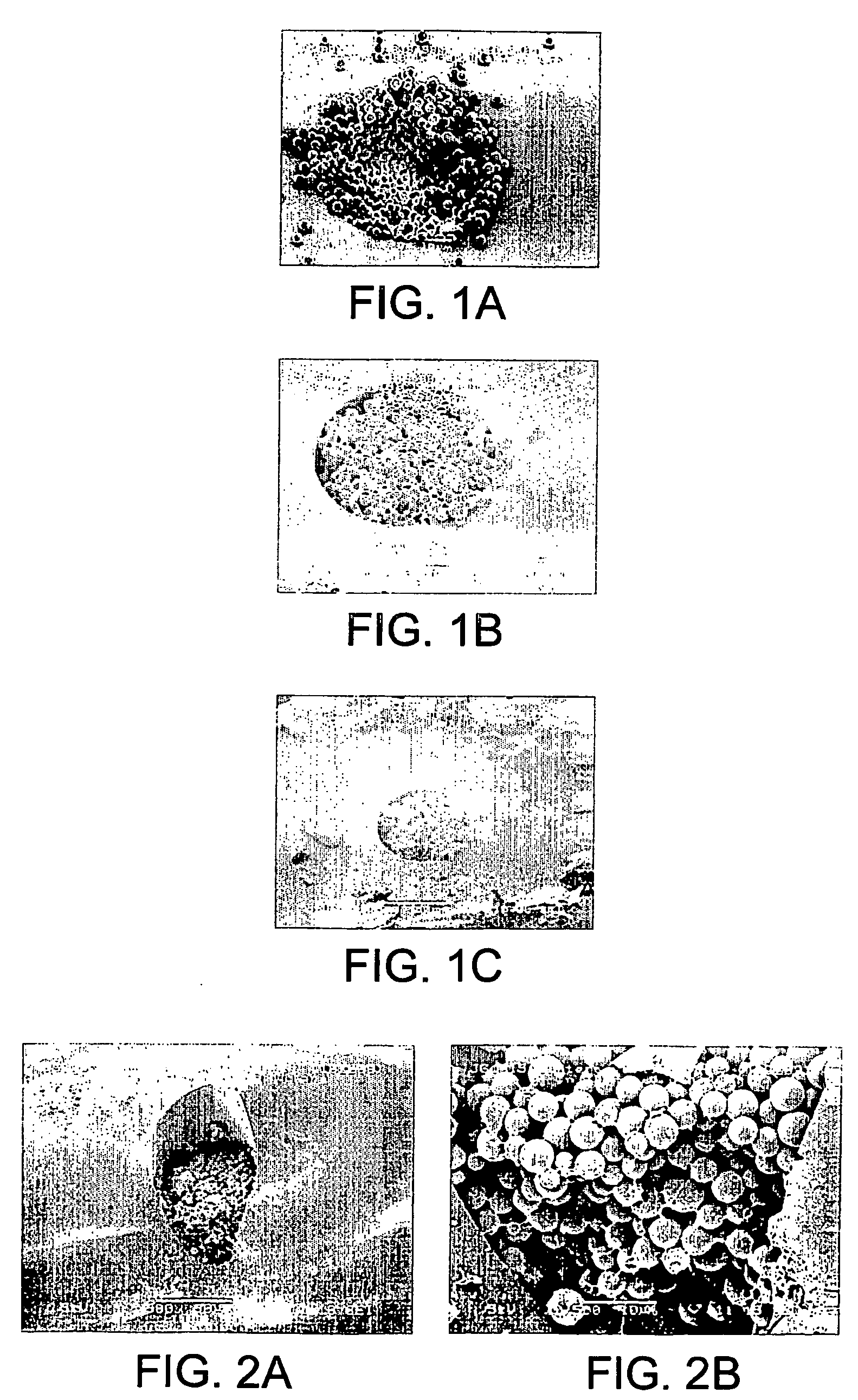
[0117] In yet another example, the slurry may be drawn into a capillary, the PDMS cured, and then sintered. A 20 cm length of 75 μm i.d. fused silica capillary was dipped into a 100 mg / mL slurry of 3.5 μm Symmetry C18 material in 5% PDMS in ethyl acetate. The capillary was allowed to dry in ambient conditions for 3 h, and was then placed in a 110° C. oven overnight. The following morning, the column frit was sintered in place using the Innovatech frit making device, discussed in Example 2. FIG. 2 presents two SEM images at magnifications of (A) 500 and (B) 2500 of a sintered PDMS frit prepared according to this example.


PUM

PropertyMeasurementUnit
Temperatureaaaaaaaaaa

Abstract

Nanocolumn chromatography devices useful, e.g., in CEC and nanoLC are disclosed. An exemplary chromatography device of the invention includes a nanocolumn, e.g., a capillary, packed with a particulate stationary phase material and a solid support. The solid support, or in situ frit, is adjacent to and integral with the stationary phase material. An in situ frit of the invention may be a mixture of the stationary phase material and a polymeric network of cross-linked poly(diorganosiloxane), e.g., poly(dimethylsiloxane), which may optionally be sintered. The invention also provides methods of making and using such devices.

Description

RELATED APPLICATIONS [0001] This application claims priority to U.S. Provisional Patent Application No. 60 / 445,725, filed Feb. 7, 2003, (attorney docket no. WCZ-037-1), and to U.S. Provisional Patent Application No. 60 / 446,399, filed Feb. 10, 2003, (attorney docket no. WCZ-037-2), the entire contents of which applications are hereby expressly incorporated herein by this reference.BACKGROUND OF THE INVENTION [0002] Several contemporary methods exist for the analytical separation of components of a mixture. In general, a liquid sample containing compounds of interest is separated by partitioning between a mobile phase and a stationary phase, and the individual separated compounds are analyzed. [0003] For example, electrophoresis, particularly capillary electrophoresis (“CE”) is a method for separation of individual molecular species from a mixture by the application of an electric field. Separation of the molecules occurs because of their different rates of movement through the soluti...

Claims


Application Information

Patent Timeline
IPC IPC(8): G01N30/02B01D15/08B01DB01J19/00B01J20/28G01N30/60
CPCB01J19/0093Y10T436/255B01J20/28057B01J20/28069B01J20/28083B01J20/281B01J20/282B01J20/283B01J20/284B01J20/285B01J20/286B01J2220/54B01J2220/84G01N30/603G01N30/6095B01J20/28026G01N30/60
Inventor GRANGER, JENNIFERHPLUMB, ROBERT
Owner WATERS TECH CORP
Why Eureka
Try Eureka