
Waveguide - printed wiring board (PWB) interconnection

a printed wiring board and waveguide technology, applied in the field of radio frequency (rf) interconnection techniques, can solve the problems of relatively complicated assembly requiring precision parts, high implementation complexity, reliability concerns, etc., and achieve the effects of reducing (or in some cases even minimizing) leakage signals, improving sensitivity, and reducing complexity

Active Publication Date: 2006-07-06
VALEO RADAR SYST
View PDF67 Cites 34 Cited by
  • Summary
  • Abstract
  • Description
  • Claims
  • Application Information

AI Technical Summary

Benefits of technology

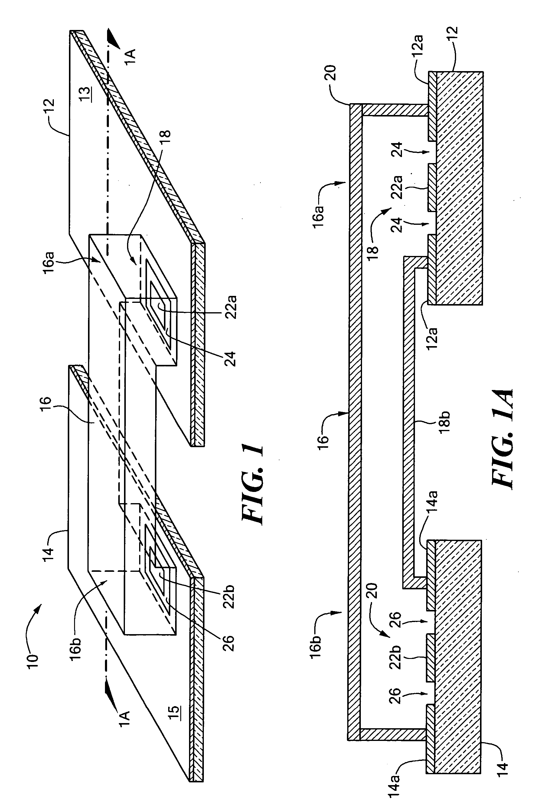
[0008] With this particular arrangement, a low cost and reliable signal path suitable for use between a plurality of RF Printed Wiring Boards (PWBs) is provided. In one embodiment, the transmission line is provided as a waveguide transmission line and the first and second feed circuits are provided as waveguide feed circuits. By providing the feed circuits as integral portions of the PWBs, the feed circuits can be provided as part of the circuit layouts for each the PWB's. Thus, no additional connecting hardware is needed to couple the PWBs to the transmission line. Moreover, the signal path is suitable to couple RF signals between each of the PWBs. In the case where the transmission line is provided as an RF transmission line, the RF feed circuits can be provided as printed circuits (e.g. patch radiator feed circuits) on part of the PWBs. Alternatively, the RF feed circuits can be provided as edge launch waveguides coupled to the PWBs or as launch pins projecting from a surface of the PWBs. Alternatively still, the RF feed circuits can be provided from coaxial line PWB transmission lines.
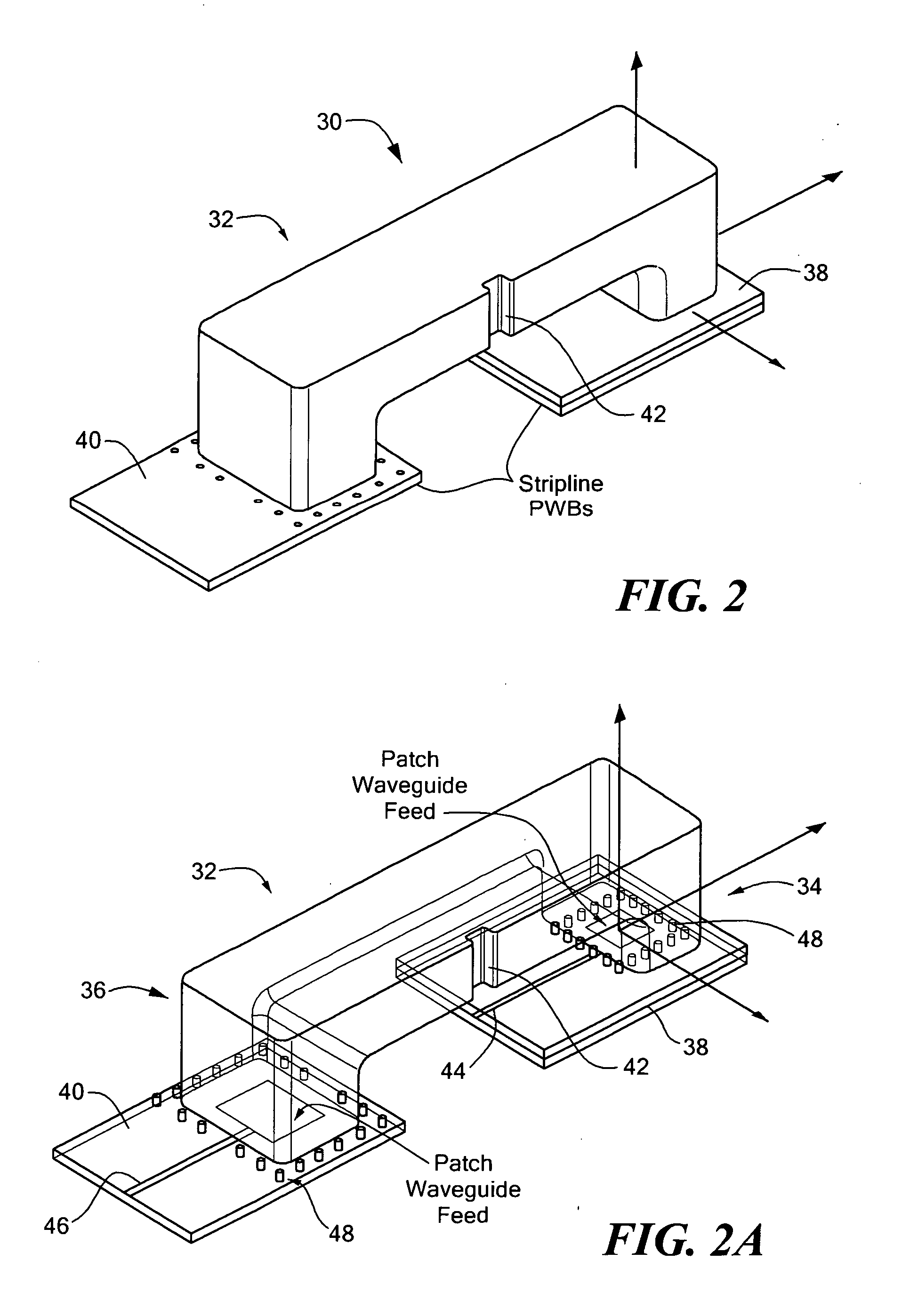
[0010] With this particular arrangement, an RF assembly having a PWB frame which supports multiple PWBs and which includes at least a portion of an integral RF waveguide signal path is provided. The PWBs include integral feed circuits used to couple RF signals between the waveguide portion of the frame and the PWBs. Other PWBs disposed on the frame can form all or some of top or side portions of the waveguide signal path. If PWB frame and the PWBs are already part of an existing module and assembly process, the module can be made less expensively and more reliably via inclusion of the integrated waveguide—PWB interconnection in the existing frame and PWB parts.
[0013] With this particular arrangement, an RF assembly having an RF signal path between multiple PWBs or between two different locations on a single PWB is provided. By providing the waveguide portion as an integral part of the PWB frame RF and providing the feed circuits as an integral part of the PWBs, the RF signal path has a relatively small impact on the overall cost of the RF assembly. The PWBs on which the feed circuits are integrated can be provided as any type of PWB (e.g. soft substrate, LTCC, etc) and the frame can be provided from any material suitable to support the PWBs including but not limited to metal, plastic and composite materials.
[0014] The PWB frame also includes alignment posts and surfaces to aid in properly aligning the PWBs in the frame. This approach helps ensure consistent RF performance by ensuring that the RF feed circuits on the PWBs are properly aligned with desired regions (i.e. waveguide port regions) of the integrated waveguide.
[0016] In some systems it is desirable to separate transmit and receive boards to reduce (or in some cases even minimize) leakage signals between transmit and receive antennas. Separating PWBs (e.g. transmit and received PWBs) and transit and receive antennas reduces leakage signals between the antennas and PWBs and allows automotive radar sensors and other systems to have improved sensitivity, improved near range performance as well as a simple and consistent threshold setting and higher production throughput. Thus, this technique allows automotive radar sensors to achieve a relatively high level of performance.
[0017] Since the RF interconnections and related techniques described herein are reliable and cost effective, it is possible to separate transmit and receive PWBs in a radar system without significantly increasing system cost and complexity. Moreover, the integrated RF signal path described herein provides a reliable RF signal path between PWBs with relatively little, if any, added cost in parts or assembly. Thus, this approach reduces cost without reducing system reliability.

Problems solved by technology

Both of these techniques are troubled by implementation complexity, reliability concerns, as well as cost issues.
Although this type of connection results in a relatively high level of performance, it is a relatively complicated assembly requiring precision parts.
Although this approach has fewer parts, the flex-print circuit is relatively expensive because of the need to include ground planes and via holes to achieve desired isolation levels.
Furthermore, it is relatively difficult to obtain a good electrical seal around a flex circuit and this makes it difficult to achieve a desired level of isolation between the PWBs being connected through the flex circuit.
More, in high frequency applications, the losses through this type of structure can be relatively high.

Method used


Image

  • Waveguide - printed wiring board (PWB) interconnection
  • Waveguide - printed wiring board (PWB) interconnection
  • Waveguide - printed wiring board (PWB) interconnection

Examples


Embodiment Construction

[0035] Referring now to FIGS. 1 and 1A in which like elements are provided having like reference designations, an RF interconnection 10 between first and second radio frequency (RF) Printed Wiring Boards (PWBs) 12, 14 (also sometimes referred to as printed circuit boards or PCBs) includes a waveguide transmission line 16 having first and second ends 16a, 16b (also referred to as waveguide port apertures or more simply waveguide ports) and pair of waveguide feed circuits 18, 20 disposed to launch signals into and couple signals out of the transmission line 16 at ends 16a, 16b, respectively.

[0036] The feed circuits 18, 20 are each provided as an integral part of at least a portion of the PWBs 12, 14 respectively. In the exemplary embodiment shown in FIGS. 1 and 1A, the feed circuits 18, 20 are provided as radiating elements and in particular are provided as micro-strip (or so-called “patch”) antenna elements on PWB surfaces 12a, 14a. Each patch is provided from a conductive region 22...


PUM


Abstract

An RF interconnection between RF Printed Wiring Boards (PWBs) includes a waveguide transmission line coupled between the RF PWBs. The waveguide feeds are provided as integral parts of each PWB. In one embodiment, the waveguide interconnecting the PWBs is provided as an integral part of a support structure which supports the PWBs. By providing the interconnecting waveguide and the feeds at each end of the waveguide as integral pieces of other already existing structures, a reliable, low cost RF interconnection between RF PWBs having relatively few separate pieces is provided.

Description

CROSS-REFERENCE TO RELATED APPLICATIONS [0001] Not applicable. STATEMENTS REGARDING FEDERALLY SPONSORED RESEARCH [0002] Not applicable. FIELD OF THE INVENTION [0003] This invention relates generally to radio frequency (RF) interconnection techniques and more particularly to techniques and structures for transmitting RF signals between printed wiring boards (PWBs). BACKGROUND OF THE INVENTION [0004] As is known in the art, in some applications it is necessary to couple radio frequency (RF) signals between multiple printed wiring boards (PWBs). Such connections are often made by using either a coaxial cable or a printed shielded RF conductor circuit (also referred to as a flex circuit). Both of these techniques are troubled by implementation complexity, reliability concerns, as well as cost issues. [0005] A coaxial cable connection typically requires the mounting of a connecting pin on the PWB. The coaxial cable shield is stripped to expose a section of a center conductor which is the...

Claims


Application Information

Patent Timeline
IPC IPC(8): H01P5/107
CPCH01P5/107H05K1/0237H05K1/14G01S2013/9321G01S7/03G01S13/931G01S2007/027G01S7/027
Inventor PLEVA, JOSEPH S.DONOVAN, RICHARD P.LEBLANC, STEPHEN P.
Owner VALEO RADAR SYST
Learn More