Method and apparatus for pixel display and SERS analysis

a pixel display and ser technology, applied in the field of light amplifiers, can solve the problems of ineffective surface study, narrow viewing angle of conventional lcds,

Active Publication Date: 2006-07-06
HEWLETT PACKARD DEV CO LP
View PDF46 Cites 18 Cited by
  • Summary
  • Abstract
  • Description
  • Claims
  • Application Information

AI Technical Summary

Benefits of technology

[0013] While the specification concludes with claims particularly pointing out and distinctly claiming that which is regarded as the present invention, the advantage

Problems solved by technology

Unfortunately, conventional LCDs do not have a wide viewing angle.
While conventional Raman Spectroscopy is suitable for bulk chemical analysis, it is not effective for surface studies because the signal from the bulk Raman scattered photons overwhelms any signal from Raman scattered photons near the surface.

Method used


Image

  • Method and apparatus for pixel display and SERS analysis
  • Method and apparatus for pixel display and SERS analysis
  • Method and apparatus for pixel display and SERS analysis

Examples


Embodiment Construction

[0027] In the detailed description, various references may be made using directional indicators such as top, bottom, side, up, and down. These directional indicators are used to assist in describing the various structures of the present invention and do not imply that the present invention must be oriented as described unless otherwise noted.

[0028] The present invention, in a number of embodiments, includes structures and irradiation devices for generating an amplified radiation, which may be useful in applications such as display devices and systems for Surface Enhanced Raman Spectroscopy (SERS) analysis.

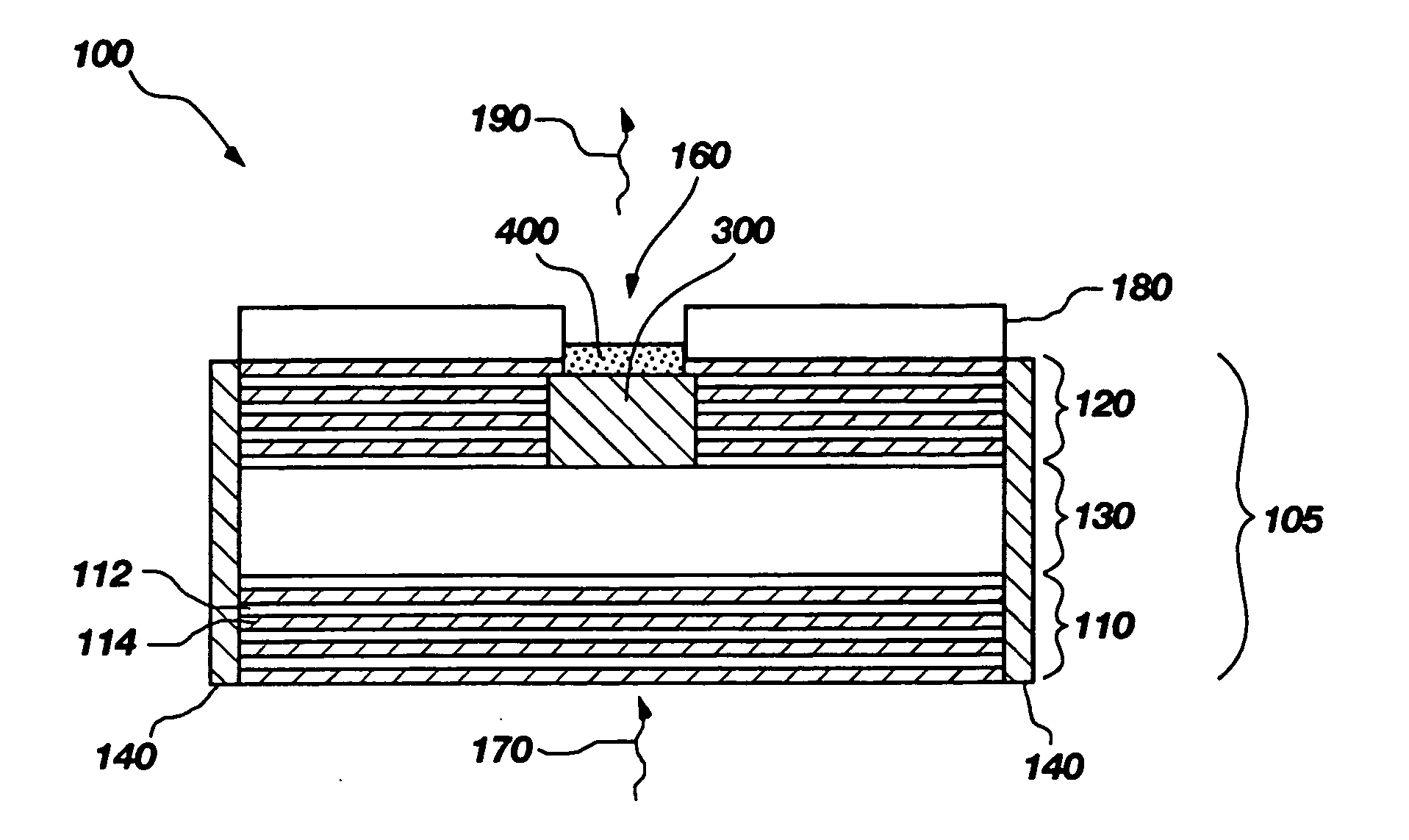
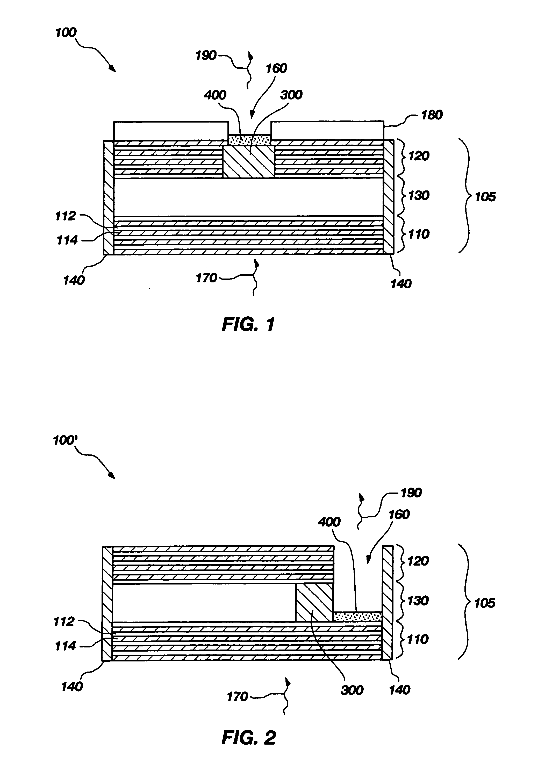
[0029]FIG. 1 illustrates an exemplary irradiation device 100 including an optical waveguide 105, an optical modulator 300, an exposure region 160 for receiving amplified radiation from the optical waveguide 105, and a medium of interest 400 for exposure to the amplified radiation. When the present invention is practiced as a display device, the medium of interest 400 may be vario...


PUM


Abstract

Irradiation devices and methods of amplification and irradiation are disclosed for displaying pixels and Surface Enhanced Raman Spectroscopy (SERS) analysis. The devices include an optical modulator, which may be configured for operation in a variably transmissive state. An active region may be formed in an optical waveguide with the optical modulator configured substantially adjacent at least one surface of the active region.

Description

FIELD OF THE INVENTION [0001] The present invention relates to light amplifiers and, more particularly, to light amplifiers for use in display devices and chemical analysis using Surface Enhanced Raman Spectroscopy (SERS). BACKGROUND OF THE INVENTION [0002] In the area of display devices, flat panel devices are increasingly replacing Cathode Ray Tubes (CRTs) in many computer and television applications. Conventional flat panels, such as Liquid Crystal Displays (LCDs) and plasma displays are becoming cost effective for many applications. At present, LCDs are one of the most popular and mature technologies for low power and cost effective implementations. [0003] Unfortunately, conventional LCDs do not have a wide viewing angle. In other words, when the viewing direction shifts away from perpendicular to the viewing screen, the light intensity and contrast perceived from the screen decreases. As a result, appearance of the image on the LCDs may change as the viewing angle changes. Rece...

Claims


Application Information

Patent Timeline
IPC IPC(8): G02B6/00
CPCG01J3/02G01J3/021G01J3/0256G01J3/10G01J3/44G01N21/658G02B2006/1213H01S5/1032H01S5/105H01S5/18302H01S5/18394H01S5/2027H01S5/11
Inventor WANG, SHIH-YUANISLAM, M. SAIF
Owner HEWLETT PACKARD DEV CO LP
Why Eureka
Try Eureka