
Dynamic control of planck radiation in photonic crystals

a technology of photonic crystals and radiation sources, applied in the field of dynamic control of planck radiation in photonic crystals, can solve the problems of limited output power of conventional thz sources, complex optical networks and cooling systems, and large lasers, and achieve the bandwidth and frequency agility to source electromagnetic energy at thz and other frequencies

Active Publication Date: 2006-07-06
RAYTHEON CO
View PDF7 Cites 15 Cited by
  • Summary
  • Abstract
  • Description
  • Claims
  • Application Information

AI Technical Summary

Benefits of technology

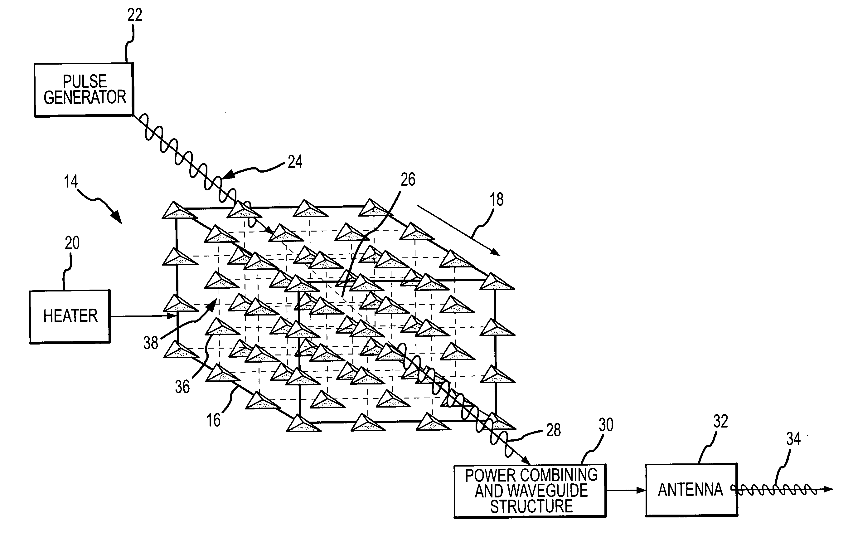
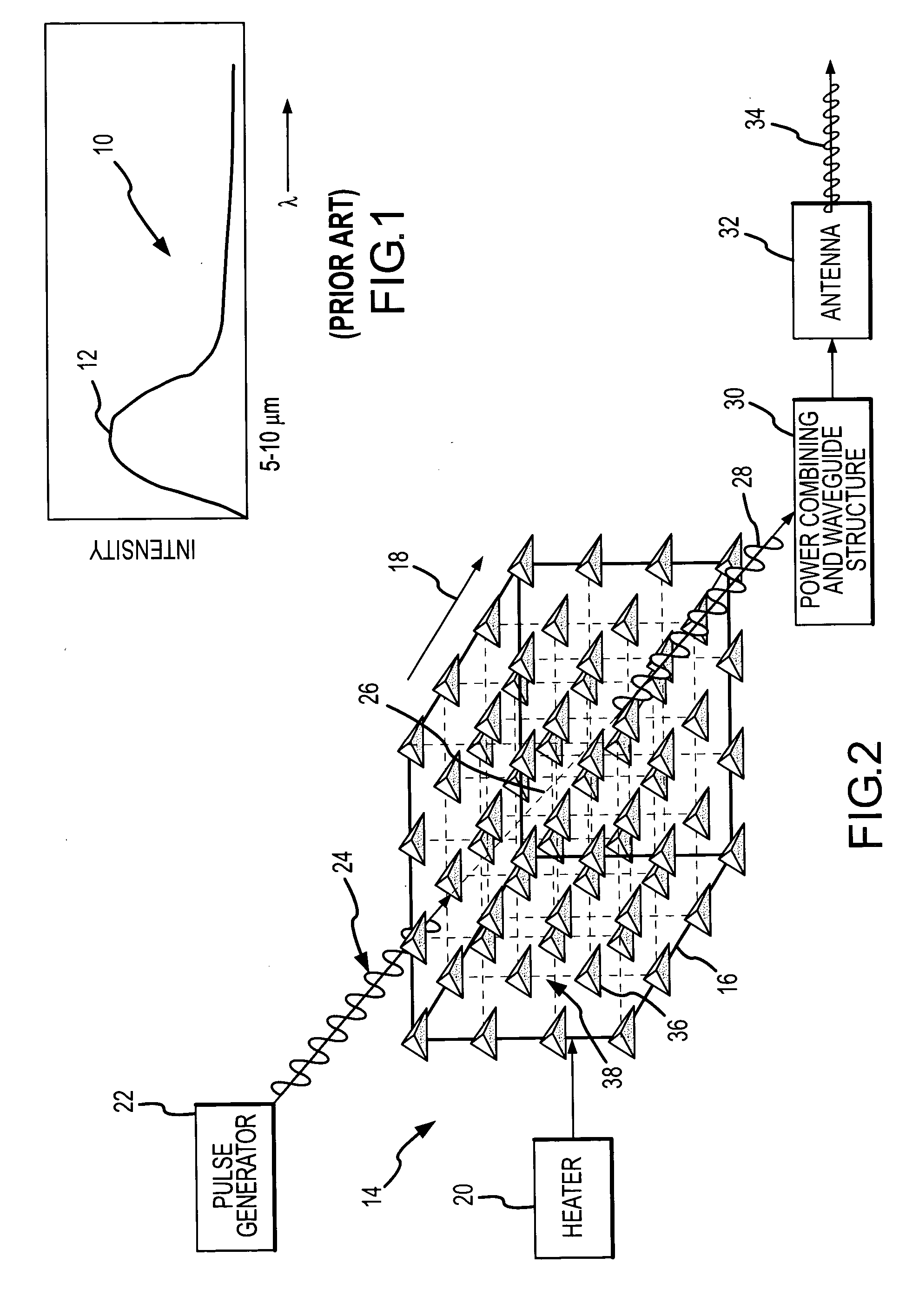
[0011] The present invention provides a method of designing and dynamically controlling a PC to modify the Planck spectral distribution of thermal electromagnetic radiation, and more specifically to shift the primary emission wavelength and reshape the distribution to concentrate more energy around the shifted peak. This approach uses the internal heat energy of a PC to configure a compact, reliable and low-cost source with the bandwidth and frequency agility to source electromagnetic radiation at THz and other frequencies. These sources will have great impact in many applications such as biological and / or chemical sensing, biomedical and other imaging systems, spectroscopy, unmanned aerial vehicle systems, and automated traffic products.

Problems solved by technology

One of the major bottlenecks for the successful implementation of THz-frequency systems has been the limited output power of conventional THz sources.
Most systems produce THz radiation via optical techniques, but those require massive lasers, complex optical networks and cooling systems.
None of these approaches offers a compact, reliable and low-cost radiation source, nor the bandwidth and frequency agility to source electromagnetic energy at THz and other frequencies.

Method used


Image

  • Dynamic control of planck radiation in photonic crystals
  • Dynamic control of planck radiation in photonic crystals
  • Dynamic control of planck radiation in photonic crystals

Examples


Embodiment Construction

[0027] The present invention describes how to design and dynamically control a PC to modify the Planck spectral distribution of thermal electromagnetic radiation, and more specifically to shift the primary emission wavelength and reshape the distribution to concentrate more thermal energy around the shifted peak. This approach is useful to configure a compact, reliable and low-cost source with the bandwidth and frequency agility to supply electromagnetic energy at THz and other frequencies. These sources will have great impact in many applications, e.g., biological and / or chemical sensing, biomedical and other imaging systems, spectroscopy, unmanned aerial vehicle systems, training devices and automated traffic products.

[0028] Li supra and Lin supra teach designing the DOS to suppress radiation emissions in the IR region and significantly enhance thermal radiation emissions in the visible waveband (approximately 0.5 μm). These principles were extended to shift the peak radiation to...


PUM


Abstract

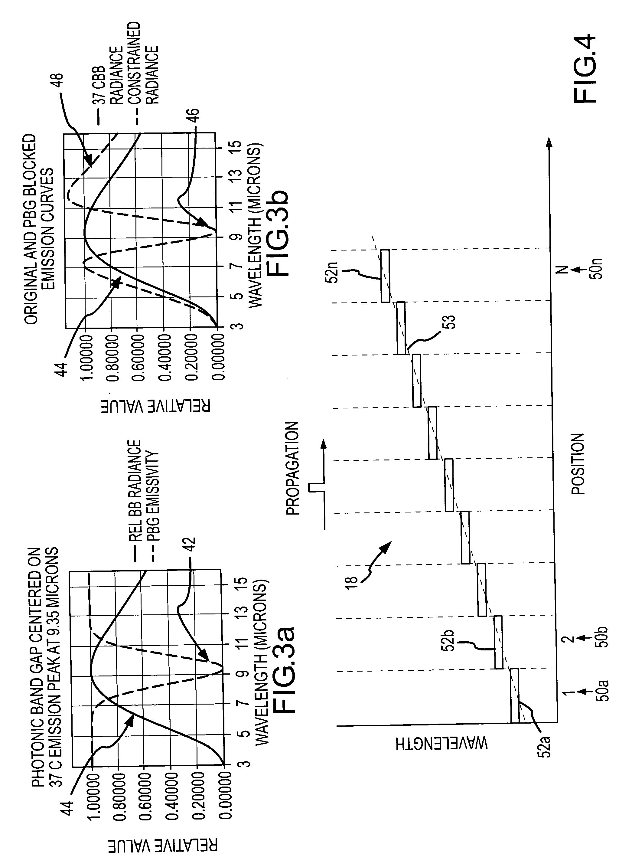
A band gap discontinuity is propagated across a Photonic Crystal (PC) to capture thermal energy in a region near the primary emission wavelength of the Planck spectral distribution and transfer that energy to a different spectral region where it is emitted. To extend the range of frequency shifting beyond the width of a single band gap, the intrinsic control parameters (e.g., lattice geometry factors, scattering element geometric factors, and variations in the index of refraction) are spatially varied across the PC to form a band gap gradient. Propagation of the band gap discontinuity, starting in the infrared wavelength region where the thermally generated electromagnetic energy is concentrated and propagating towards the long wavelength region, locally captures the thermal electromagnetic radiation, shifts it downwards in frequency, and pushes the lower-frequency thermal electromagnetic radiation on to the next region. The same principles apply to shift the frequency to shorter wavelengths. A PC-based power combining and waveguide structure can be constructed in the same or a surrounding structure to combine and guide the shifted radiation to an antenna or exit aperture.

Description

CROSS-REFERENCE TO RELATED APPLICATIONS [0001] This application claims benefit of priority under 35 U.S.C. 120 to U.S. application Ser. No. 10 / 960,679 entitled “Thermally Powered Terahertz Radiation Source Using Photonic Crystals” and filed on Oct. 7, 2004, the entire contents of which are incorporated by reference.BACKGROUND OF THE INVENTION [0002] 1. Field of the Invention [0003] This invention relates to the use of Photonic Crystals as a source of electromagnetic radiation at THz or other frequencies, and more specifically to dynamically propagating a band gap discontinuity through a Photonic Crystal to modify the spectral distribution of thermal electromagnetic radiation. [0004] 2. Description of the Related Art [0005] At quite modest temperatures, small objects possess significant free energy, which is emitted in the form of thermal electromagnetic radiation across a broad spectral band, including visible, infrared (IR), THz, etc. For a perfect blackbody emitter, the thermal el...

Claims


Application Information

Patent Timeline
IPC IPC(8): H04B10/00
CPCB82Y20/00G02B6/1225
Inventor ROSENWALD, ROSS D.SHAH, NITESH N.BARKER, DELMAR L.OWENS, WILLIAM R.XIN, HAO
Owner RAYTHEON CO
Learn More