Method for making ePTFE and structure containing such ePTFE. such as a vascular graft

a technology of eptfe and vascular graft, which is applied in the field of making structures, can solve the problems of increasing the difficulty of further radial expansion of such a fully sintered eptfe tube structure, difficulty in further expansion, and difficulty in further radial expansion, so as to facilitate subsequent radial expansion, increase the resistance to tears, and improve the yield of useful products

Inactive Publication Date: 2006-07-06
LIFESHIELD SCI
View PDF83 Cites 25 Cited by
  • Summary
  • Abstract
  • Description
  • Claims
  • Application Information

AI Technical Summary

Benefits of technology

[0007] The partial sintering of the ePTFE structure which has been initially expanded facilitates the subsequent expansion thereof. For example, partial sintering of a longitudinally expanded ePTFE tube structure facilitates subsequent radial expansion thereof. This results from the node and fibril micro-structure produced from the initial longitudinal expansion and the partial sintering being deformable and having an increased resistance to tears and the like during such deformation. This provides higher useful product yields from such subsequent radial expansion.
[0008] The partial sintering of an ePTFE tube structure which has been previously expanded is particularly advantageous for subsequent expansions thereof which are substantial in amount. In contrast, if an expanded ePTFE tube structure is fully sintered and then subsequently expanded, then considerable amounts of tears and the like in the tube structure can be expected. Accordingly, partial sintering of an ePTFE tube structure which has been longitudinally expanded facilitates subsequent radial expansion thereof where such radial expansion is desired to substantially increase the radial dimension of the tube structure. Also, radial expansion of a longitudinally expanded ePTFE tube structure which has been partially sintered is facilitated where such radial expansion is desired to produce a tapered portion of the tube structure between portions thereof which have different radial dimensions. Additionally, a component of a bifurcated ePTFE tube structure, such as an ePTFE tube structure which constitutes the trunk or one or more branches thereof, may be longitudinally expanded and subsequently radially expanded before the component is assembled to the bifurcated ePTFE tube structure. Such subsequent radial expansion is facilitated when the component is partially sintered after the longitudinal expansion and before the radial expansion thereof.
[0009] An alternative embodiment of the method of the present invention includes providing a PTFE green tube extrudate which is un-sintered, longitudinally expanding the un-sintered extrudate, and radially expanding the un-sintered, longitudinally expanded, extrudate. Radial expansion of the longitudinally expanded, un-sintered tube structure, as compared to a partially or fully sintered ePTFE tube structure, also results in higher yields because the longitudinally expanded, un-sintered tube structure is deformable and has an increased resistance to tears and the like during such deformation.

Problems solved by technology

One disadvantage of known methods of expanding an extruded PTFE green tube structure is that such methods typically provide for the green tube structure to initially be longitudinally expanded and then fully sintered.
Further expansion of such a fully sintered ePTFE tube structure, such as by radial expansion thereof, may be difficult.
Such precise control of the force application and possibly other conditions makes such further expansion difficult.
The difficulty of such further radial expansion increases as the magnitude of such expansion increases.
If further expansion of a fully sintered ePTFE tube structure is not properly performed, then significant portions of the sintered ePTFE tube structures may be damaged by such further expansion.

Method used


Image

  • Method for making ePTFE and structure containing such ePTFE. such as a vascular graft
  • Method for making ePTFE and structure containing such ePTFE. such as a vascular graft
  • Method for making ePTFE and structure containing such ePTFE. such as a vascular graft

Examples


Embodiment Construction

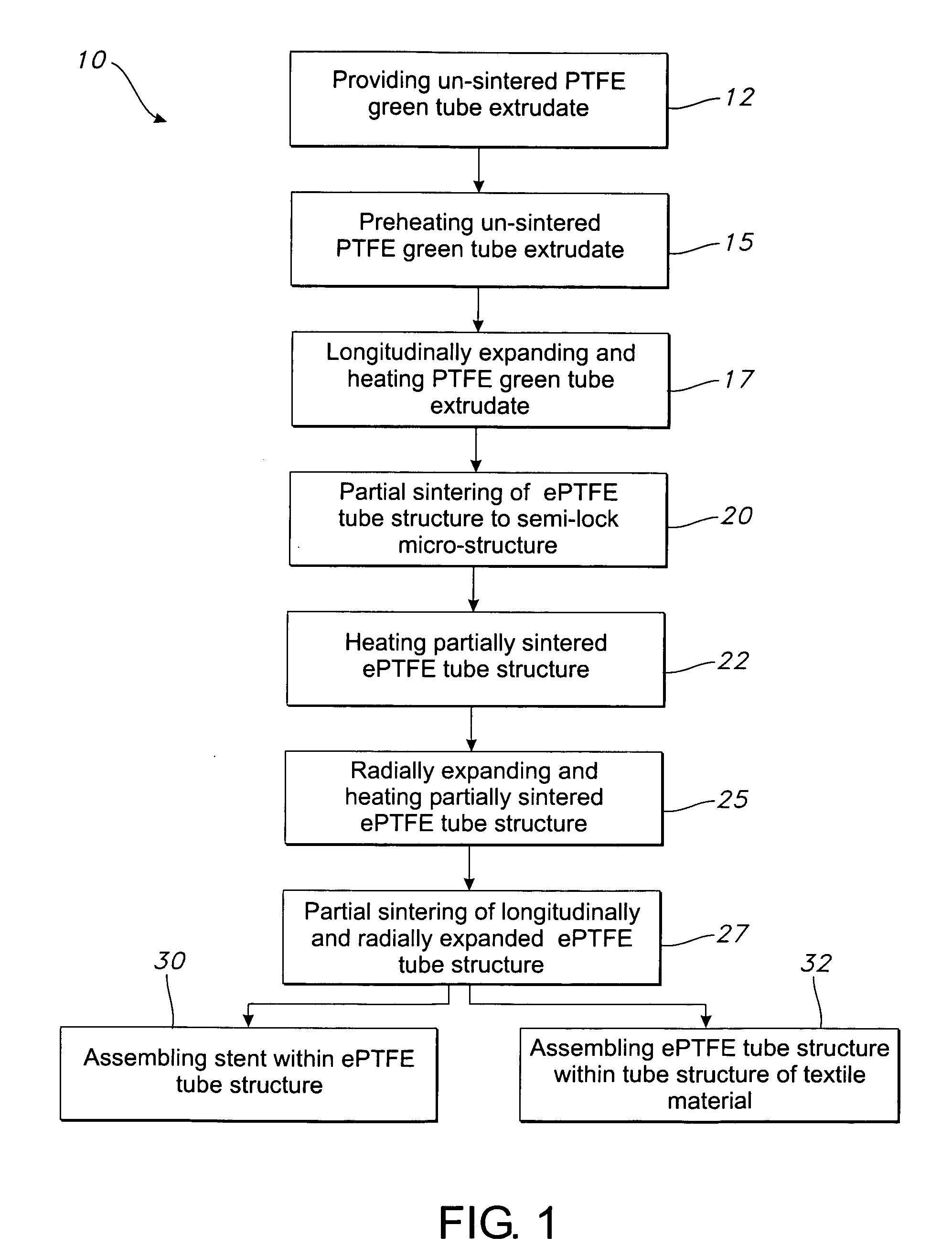
[0028] Referring to the drawings and more particularly to FIG. 1, a method 10 for making an ePTFE structure is shown in the block diagram thereof. The ePTFE structure which is made according to the method 10 is a vascular graft. Alternative embodiments of the method 10 may be used to make other ePTFE structures, such as a cover for a stent, sheet, plate, rod and mono-filament. The method 10 for making a vascular graft includes providing PTFE green tube extrudate which is un-sintered 12, and pre-heating the extrudate 15. The pre-heating 15 may be, for example, at a temperature of from approximately room temperature to 500 degrees F.

[0029] The pre-heated un-sintered PTFE green tube extrudate is longitudinally expanded with continued heating thereof 17. The continued heating may be at temperatures of up to approximately 600 degrees F., such as 500 degrees F. An expanded PTFE green tube extrudate is referred to herein as an ePTFE tube structure. The longitudinal expansion 17 may increa...


PUM

PropertyMeasurementUnit
inner diameteraaaaaaaaaa

Abstract

A method for making a vascular graft includes providing a PTFE green tube extrudate which is un-sintered, and then initially expanding the un-sintered extrudate to produce an initial node and fibril micro-structure therein. This is followed by heating the extrudate to raise the temperature thereof for a time period of sufficient duration such that the extrudate is partially sintered. The partially sintered extrudate is subsequently expanded to make the vascular graft. The subsequent expansion produces a subsequent node and fibril micro-structure in the vascular graft. An alternative method for making a vascular graft includes providing a PTFE green tube extrudate which is un-sintered, longitudinally expanding the un-sintered extrudate to form an ePTFE tube structure, and radially expanding the un-sintered ePTFE tube structure. ePTFE made according to the method is fabricated into various structures, such as tube structures, filament structures, and sheet structures.

Description

FIELD OF THE INVENTION [0001] The present invention relates generally to a method for making structures including expanded polytetrafluoroethylene (PTFE). More specifically, the present invention relates to such a method in which a PTFE structure is expanded, partially sintered and further expanded. The present invention further relates to a structure containing ePTFE made according to the method, such as an ePTFE tube structure for a vascular graft. BACKGROUND OF THE INVENTION [0002] It is well known to use extruded tube structures of polytetrafluoroethylene (PTFE) as implantable intraluminal prostheses, particularly vascular grafts. PTFE is particularly suitable as an implantable prosthesis as it exhibits superior biocompatibility. PTFE tube structures may be used as vascular grafts in the replacement or repair of a blood vessel as PTFE exhibits low thrombogenicity. In vascular applications, the grafts are manufactured from expanded polytetrafluoroethylene (ePTFE) tube structures....

Claims


Application Information

Patent Timeline
Patent Type & Authority Applications(United States)
IPC IPC(8): B32B1/08B29C47/00
CPCA61F2/07A61F2002/075A61L27/16B29C55/26Y10T428/1352B29L2031/7534B29K2027/18Y10T428/139C08L27/18
Inventor DURAN, JULIOSOWINSKI, KRZYSZTOF
Owner LIFESHIELD SCI
Why Eureka
Try Eureka