Method of forming mask and mask

Inactive Publication Date: 2006-07-06
SEIKO EPSON CORP
View PDF2 Cites 28 Cited by
  • Summary
  • Abstract
  • Description
  • Claims
  • Application Information

AI Technical Summary

Benefits of technology

[0014] According to the aspect of the invention, the alignment of the substrate with the mask may be performed while the substrate is held by an electrostatic force or vacuum. Accordingly, the substrate can be properly maintained and it is possible to minutely move the substrate to align the substrate with the mask.
[0015] According to another aspect of the invention, a mask includes a base substrate having openings and a monocrystalline silicon substrate formed on the base substrate and having opening patterns. The base substrate is aligned with the monocrystalline silicon substrate such that the opening patterns are accommodated in the openings, and non-opening portions of the base substrate are provided with a permanent magnet or a ferromagnetic substance. With th

Problems solved by technology

However, it is difficult to manufacture a highly precise mask since dimensions of the mask become too large due to plastic deformation occurring when the tension is applied.
However, since the mask becomes heavier as it becomes la

Method used


Image

  • Method of forming mask and mask
  • Method of forming mask and mask
  • Method of forming mask and mask

Examples


first embodiment

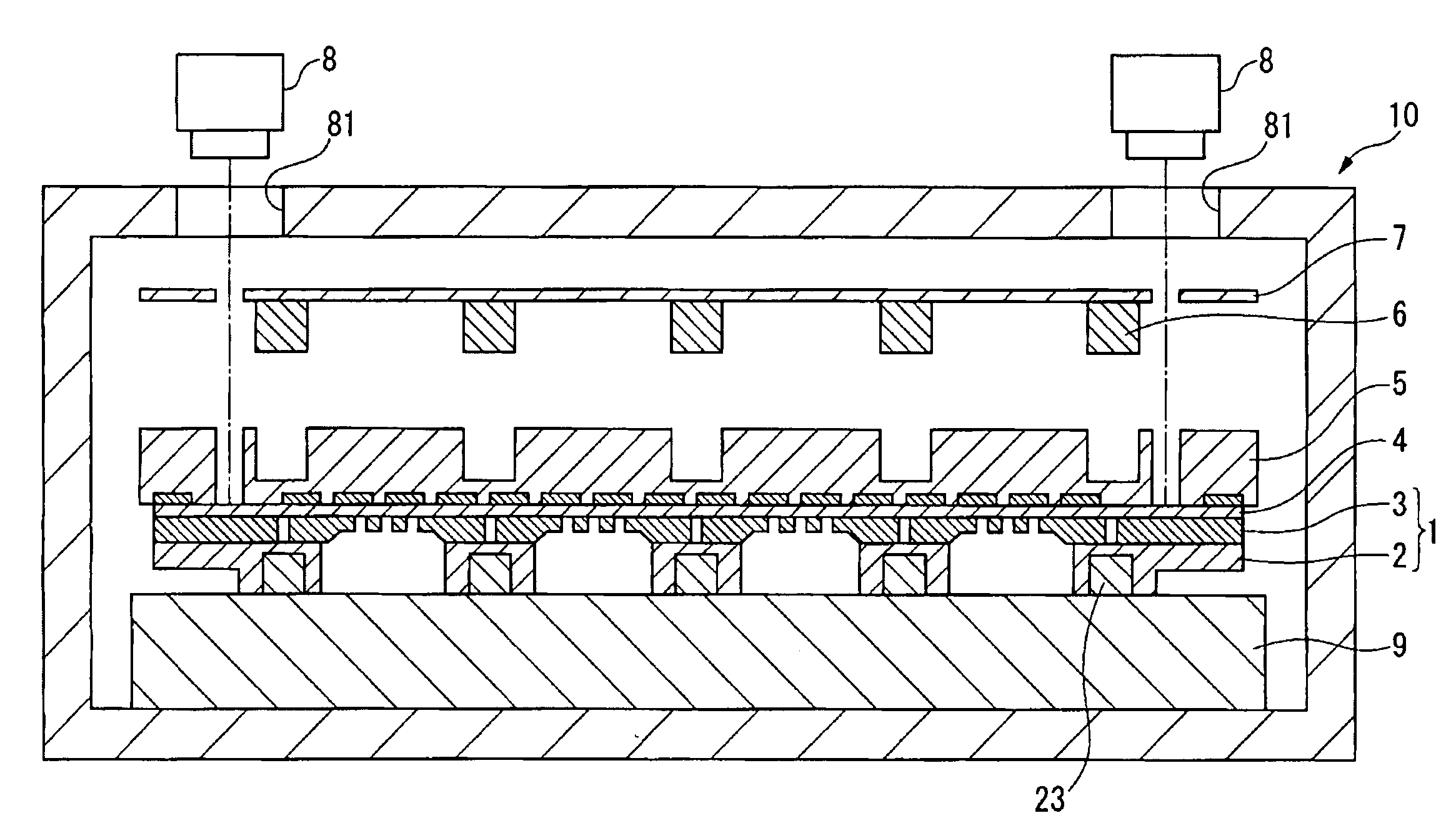
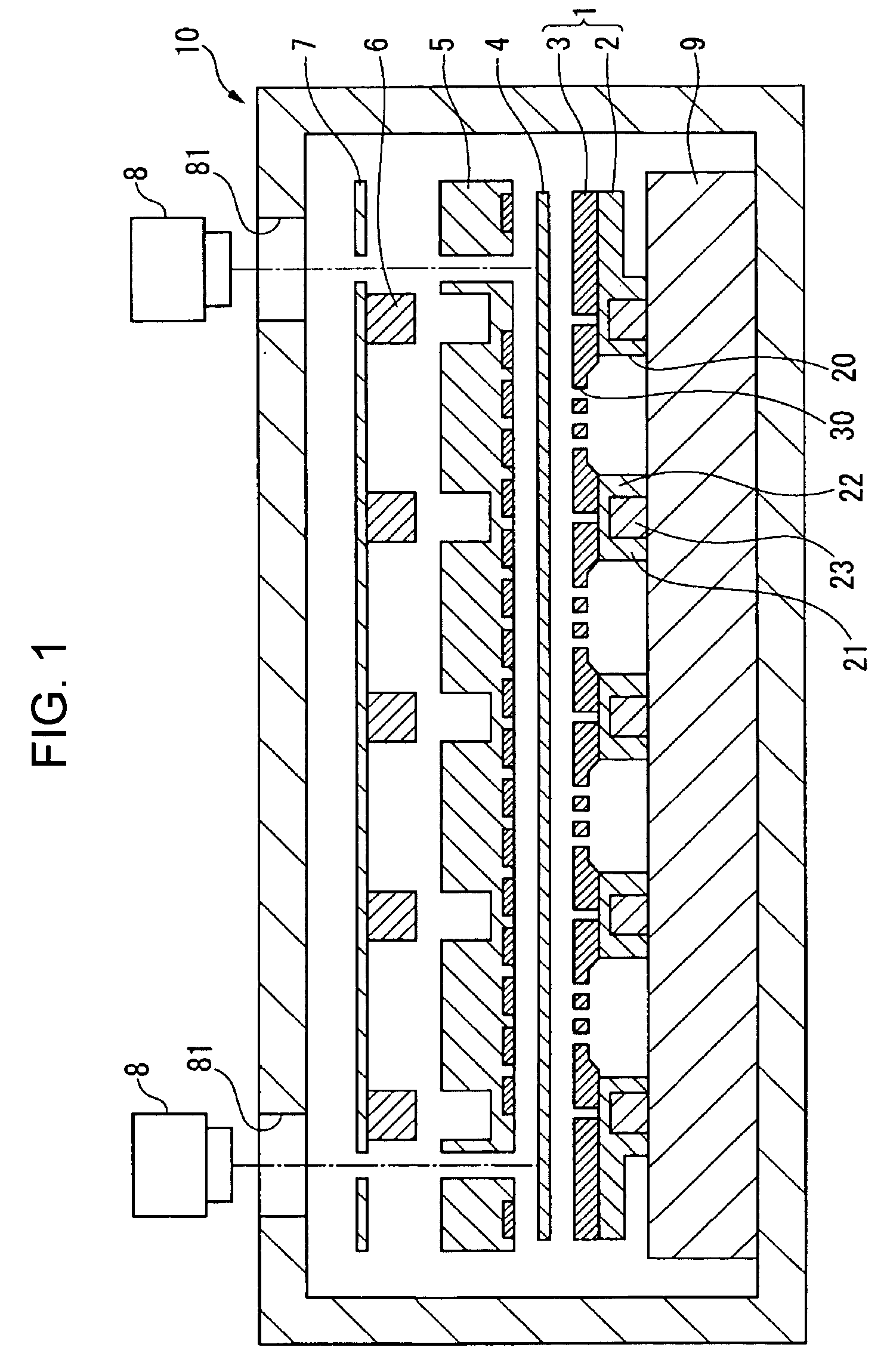
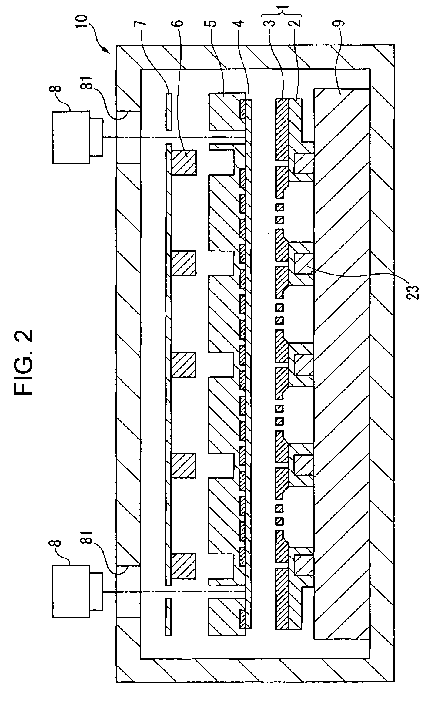
[0036] Hereinafter, a method of forming a film and a mask of the invention will be described with reference to FIGS. 1 to 10 in which a deposition method and a deposition mask according to one embodiment of the invention are shown. FIG. 1 is a schematic diagram illustrating an alignment chamber used in a deposition method according to one embodiment of the invention, and FIGS. 2 to 10 are schematic diagrams illustrating processes of the deposition method according to one embodiment. A chamber 10 shown in FIG. 1 is a chamber 10 in which a mask 1 for deposition is aligned with a substrate 4 to be deposited. A deposition process is performed in a separate chamber 11 (see FIG. 6). The deposition process performed in this embodiment is to eject deposition material upward from a source of deposition 12 (see FIG. 6) and form the ejected deposition material in the form of a film in a predetermined pattern on the substrate 4 above the source of deposition 12 (see FIG. 6).

[0037] The mask 1 i...

second embodiment

[0049] Next, a method of forming a film and a mask according to the invention will be described with reference to FIGS. 11 to 17, in which a deposition method and a deposition mask according to another embodiment of the invention are shown. FIG. 11 is a schematic diagram illustrating an alignment chamber used in a deposition method according to another embodiment of the invention, and FIGS. 12 to 17 are schematic diagrams illustrating processes of the deposition method according to the first embodiment.

[0050] A chamber 10 shown in FIG. 11 is a chamber 10 in which a mask 1 for deposition is aligned with a substrate 4 to be deposited. A deposition process is performed in a separate chamber 11 (see FIG. 17). The deposition process performed in this embodiment is to eject deposition material upward from a source of deposition 12 (see FIG. 17) and form the ejected deposition material in the form of a film in a predetermined pattern on the substrate 4 above the source of deposition 12 (s...


PUM

PropertyMeasurementUnit
Electrostatic forceaaaaaaaaaa
Magnetic forceaaaaaaaaaa

Abstract

A method of forming a mask, in which a film pattern is formed on a substrate by using a mask, includes sequentially arranging the mask, the substrate and a first member having a flat surface contacting with the substrate in this order from a supply source of film forming material; and attracting the mask and the first member by means of a magnetic force.

Description

BACKGROUND [0001] 1. Technical Field [0002] The present invention relates to a method of forming a mask and a mask, and in particular, to a method of forming a film adapted to film formation by deposition and a mask. [0003] 2. Related Art [0004] In manufacturing a large-sized full color organic electroluminescent (EL) panel used in a TV display, a highly precise deposition mask is needed and the deposition mask must be precisely aligned with a substrate to be filmed so as to be deposited. Conventionally, a metal mask made of very thin galvanoplastics has been widely used to manufacture the full color organic EL panel. Due to the metal mask having high flexibility, the metal mask must be bonded to a mask holding frame with tension so as to be used in the panel. However, it is difficult to manufacture a highly precise mask since dimensions of the mask become too large due to plastic deformation occurring when the tension is applied. Thus, a producible size of the full color organic EL...

Claims


Application Information

Patent Timeline
IPC IPC(8): H01L21/00H01L29/04
CPCC23C14/042C23C14/12H01L21/3081H01L21/3083H01L21/6831H01L51/56H10K71/00H05B33/10
Inventor YOTSUYA, SHINICHIKOEDA, HIROSHIKUWAHARA, TAKAYUKIIKEHARA, TADAYOSHI
Owner SEIKO EPSON CORP
Why Eureka
Try Eureka