

Polyaxial bone screw with multi-part shank retainer
- Summary
- Abstract
- Description
- Claims
- Application Information
AI Technical Summary
Benefits of technology
Problems solved by technology
Method used
Image

Examples
first embodiment
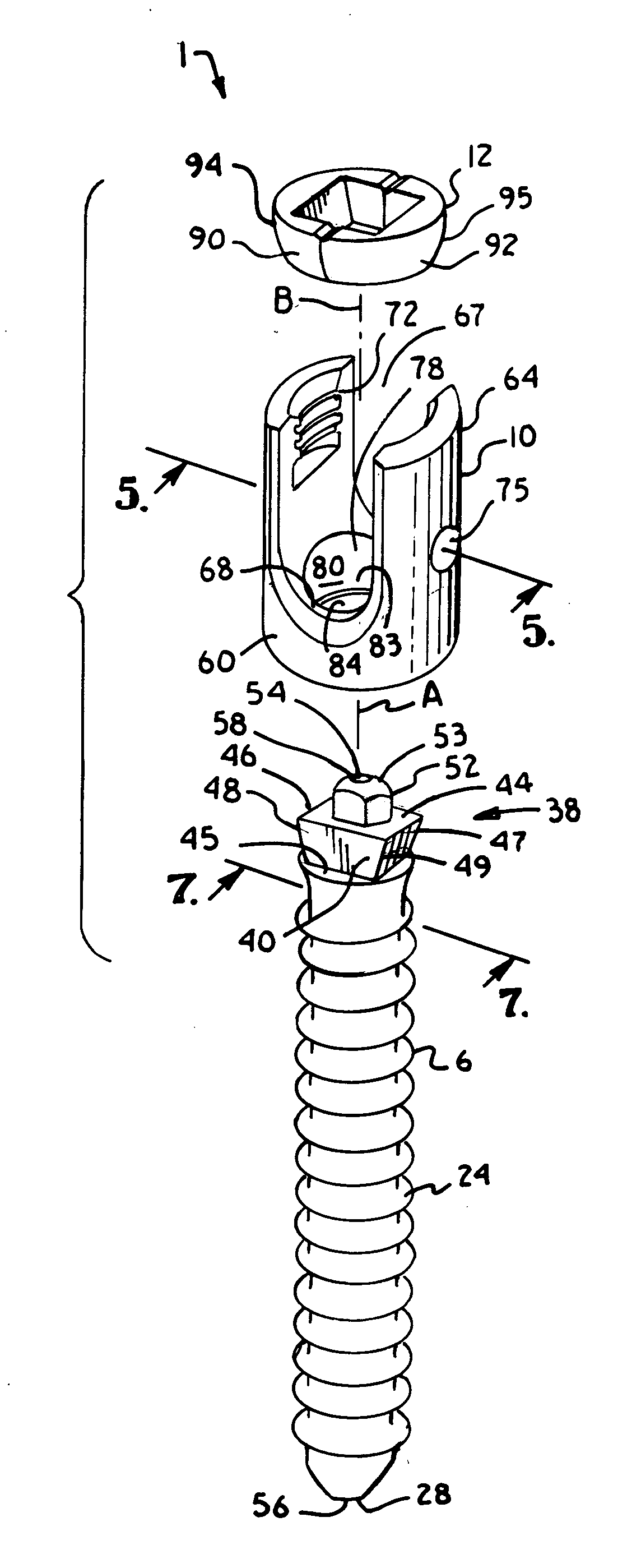
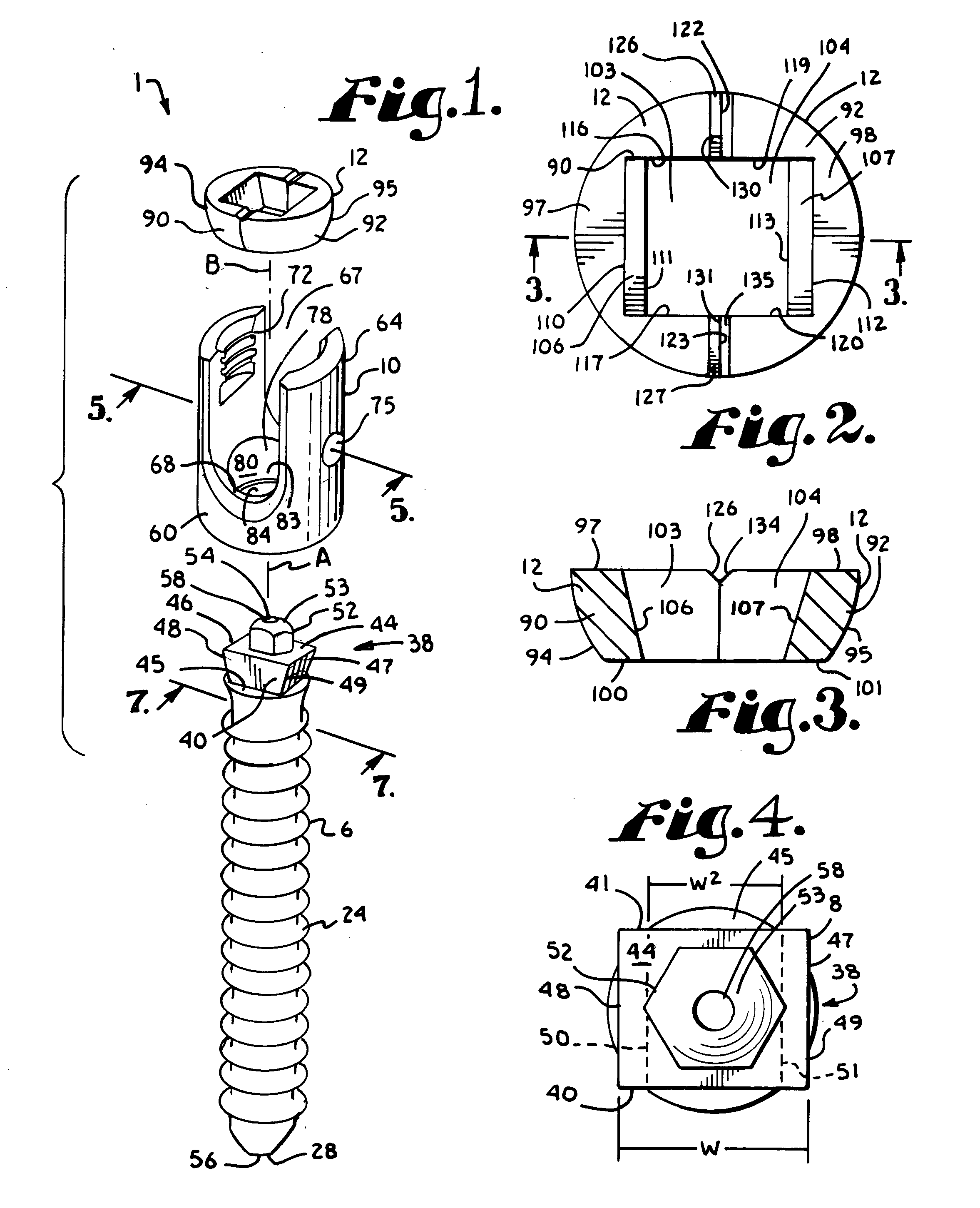
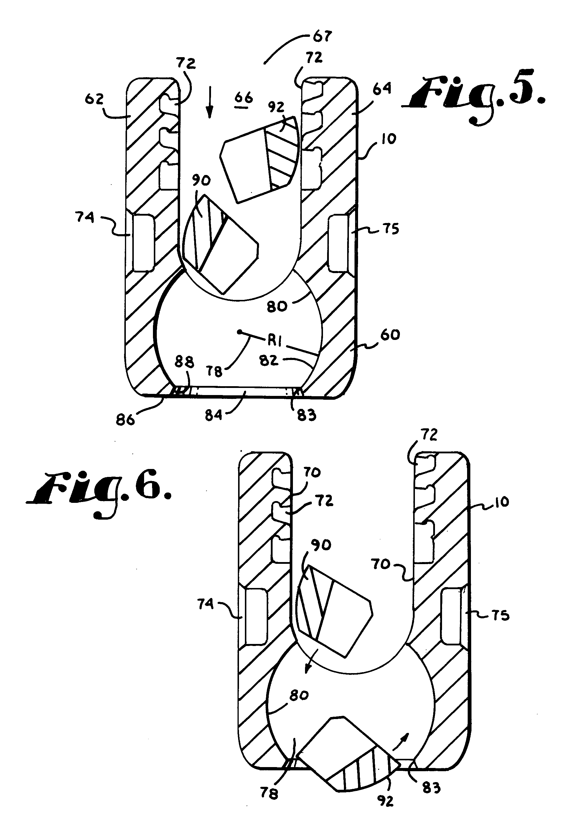
[0062] In FIGS. 1-16 the reference number 1 generally represents a polyaxial bone screw apparatus or assembly according to the present invention. The assembly 1 includes a shank, generally 4, that further includes a body 6 integral with an upwardly extending capture structure 8; a head 10; and a two-piece or part retainer structure 12. The shank 4, head 10 and retainer structure 12 preferably are assembled prior to implantation of the shank body 6 into a vertebra 15, which procedure is shown in FIG. 11.
[0063]FIG. 12 further shows a closure structure 18 of the invention for biasing a longitudinal member such as a rod 21 against the capture structure 8 which biases the retainer structure 12 into fixed frictional contact with the capture structure 8 and the head 10, so as to fix the rod 21 relative to the vertebra 15. The head 10 and the shank 4 cooperate in such a manner that the head 10 and the shank 4 can be secured at any of a plurality of angles, articulations or rotational alignm...
third embodiment
[0113] With reference to FIGS. 29-36 the reference number 301 generally represents a polyaxial bone screw apparatus or assembly according to the present invention. The assembly 301 includes a shank 304 that further includes a body 306 integral with an upwardly extending, substantially conical capture structure 308 and a two-piece or part retainer structure 312 configured to cooperate with the conical capture structure 308. The assembly further includes the head 10 of the first assembly 1 described previously herein. Therefore, all of the reference numbers previously identified with respect to the head 10 are incorporated into the drawing FIGS. 29-36 and the description thereof are incorporated by reference herein with respect to the assembly 301.
[0114] The shank 304, the head 10 and the retainer structure 312 preferably are assembled prior to implantation of the shank body 306 into a vertebra (not shown), but similar to the vertebra 15 shown in FIG. 11, and the procedure described h...
PUM
 Abstract
Description
Claims
Application Information