Fluid flow prosthetic device

a prosthetic device and fluorescence technology, applied in the field of implantable prosthetic devices, can solve the problems of increased wall tension and myocardial oxygen demand, increased left ventricular systolic pressure, and significant pressure drop across the valv

Active Publication Date: 2006-07-06
MEDTRONIC VENTOR TECH
View PDF50 Cites 955 Cited by
  • Summary
  • Abstract
  • Description
  • Claims
  • Application Information

AI Technical Summary

Benefits of technology

[0014] Further features and advantages of the invention will be apparent from the description below.

Problems solved by technology

The diminished aortic valve opening area (from normally more than 3 cm2 in an averaged sized adult to less than 0.5 cm2 in severe cases) results in a significant pressure drop across the valve, and normal cardiac output and aortic pressure can only be maintained at the expense of an increased left ventricular systolic pressure.
The high intracavitary pressure which has to be generated by the left ventricular chamber results in increased wall tension and myocardial oxygen demand.
Adaptive processes such as hypertrophy (compensatory increase in muscle mass) allow the heart to withstand this increased pressure load for some time, but ultimately, pump failure is inevitable.
Consequently, surgical mortality and morbidity are substantial.
Moreover, if the calcified aortic valve is replaced by a mechanical prosthesis, anticoagulation is mandatory to reduce thromboembolic complications, which exposes the patient to an increased risk of serious bleeding, particularly with increasing age.
Implantation of biological prostheses is therefore usually preferred in the elderly, but surgically implanted biological valves may have a suboptimal hemodynamic profile, because the suture ring on which the valve needs to be mounted reduces the space available for the valve itself.
This poses a particular problem in women, where bioprostheses of a smaller size (which have to be used because of the smaller cardiac dimensions) may result in significant residual outflow obstruction.
Unfortunately, because immediate results of the balloon dilatation are suboptimal, and recoil of the stenosis reoccurs within weeks and months in virtually all patients, outcome is as poor as in patients who do not undergo surgery.
However, this approach could result in coronary artery occlusion when undertaken in the aortic position, which would be fatal to the patient.
Even when the stent is not deployed across the full area of the aortic annulus, atheromatous deposits on the ventricular side of the aortic cusps (or leaflets) may be pushed against the ostia of the coronary arteries causing severe coronary obstruction or embolization.
Severe distention of a heavily calcified aortic valve to allow deployment of a sizeable stent may also cause embolization of calcium deposits from the valve or a tear in the valve resulting in significant aortic regurgitation.
Furthermore, a large stent-valve may also interfere with surrounding structures such as the anterior mitral leaflet (causing damage to it or impairing its function), and if protruding into the left ventricular outflow tract, the basal ventricular septum, which is usually hypertrophied in significant aortic stenosis.

Method used


Image

  • Fluid flow prosthetic device
  • Fluid flow prosthetic device
  • Fluid flow prosthetic device

Examples


Embodiment Construction

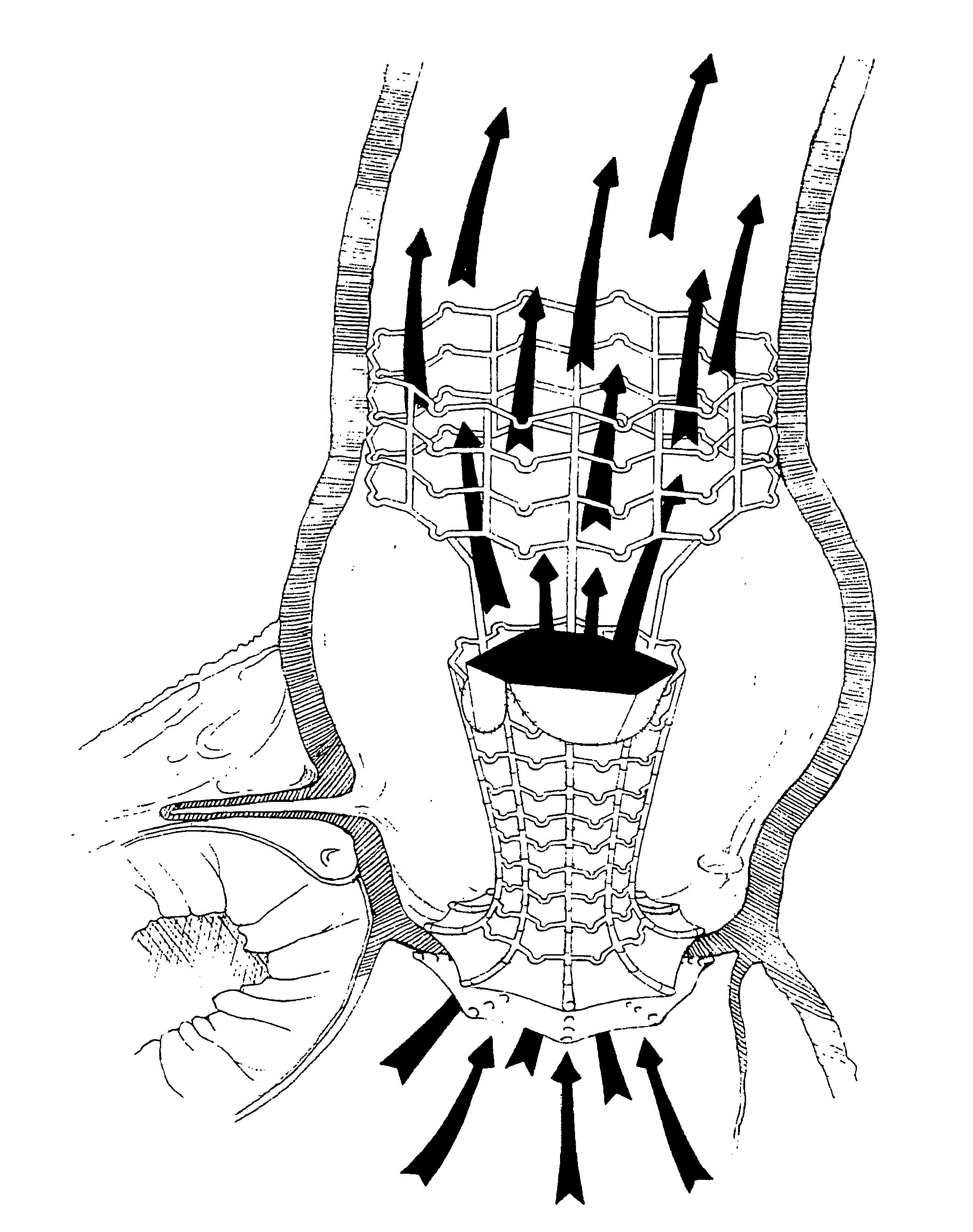
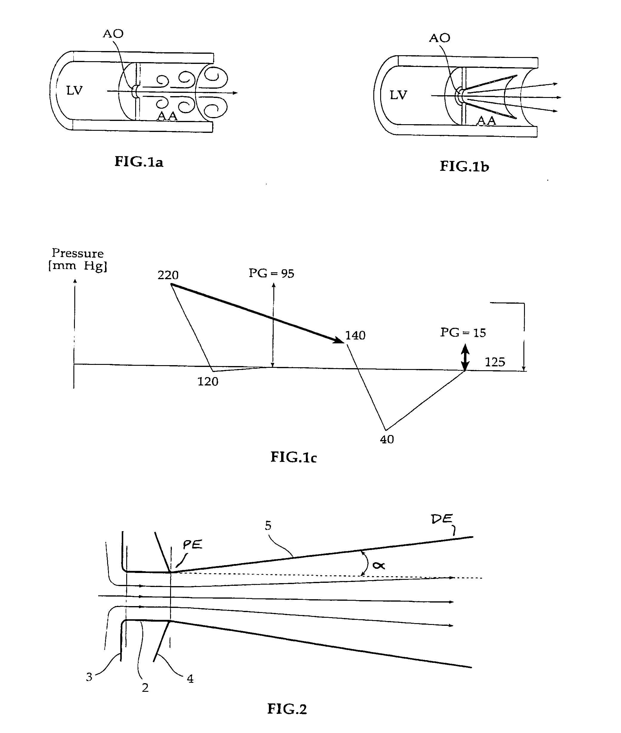
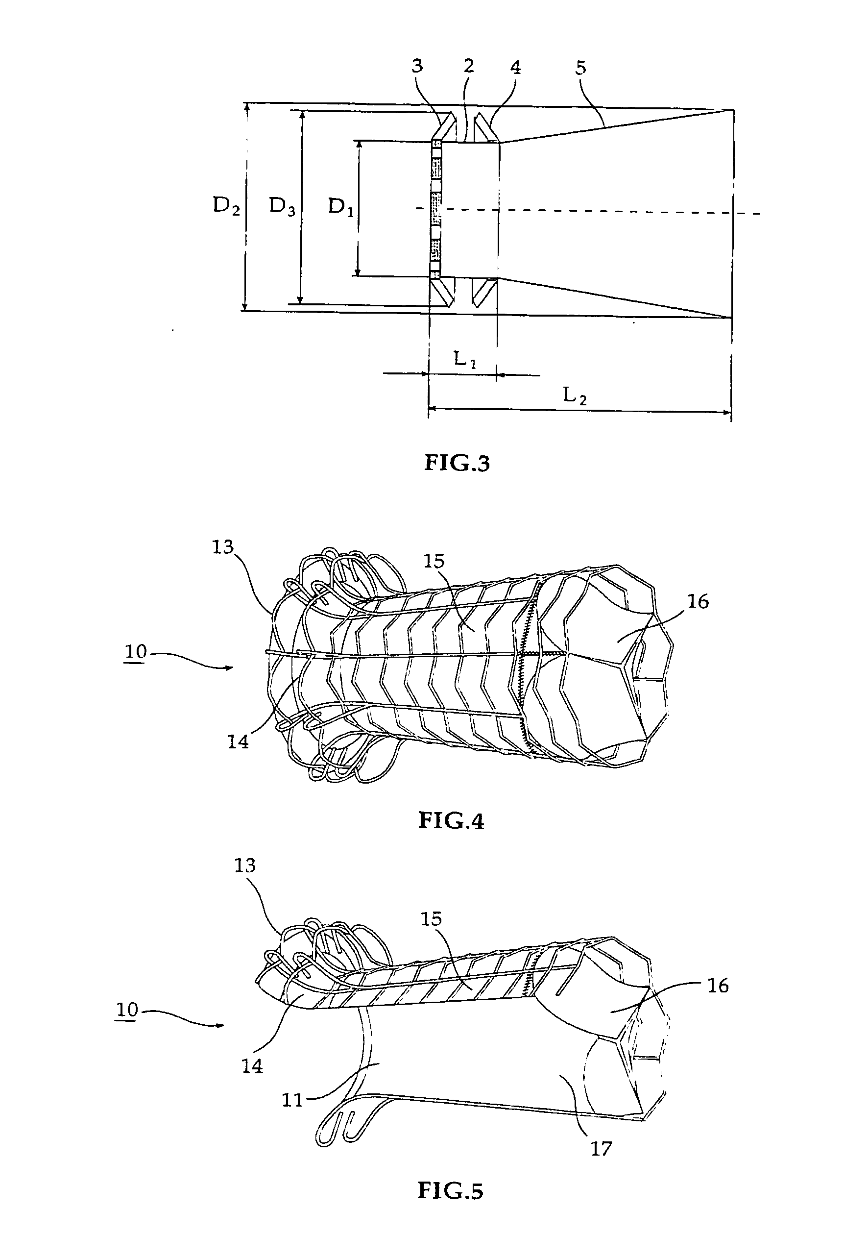
[0036] Reference is now made to FIG. 2, which diagrammatically illustrates one non-limiting construction of a prosthetic device in accordance with the present invention, and FIGS. 1A-1C, which diagrammatically illustrate the manner in which such a prosthetic device may be used for alleviating the work load placed on the heart by an aortic valve suffering from significant aortic stenosis. It is noted that the present invention is not dependent upon any theory or explanation of the manner in which the blood flows in the circulatory system, and any explanation or theory is provided simply for the purposes of elucidation. It is also noted that the embodiments described in detail hereinbelow are only exemplary and the invention is not limited to these specific constructions.

[0037] The principles of flow regulation in the cardiovascular system may be similar to those in pipeline systems. Aortic pressure and cardiac output are regulated by the baroreceptor-system with its stretch-receptor...


PUM


Abstract

A prosthetic device including a valve-orifice attachment member attachable to a valve in a blood vessel and including a fluid inlet, and a diverging member that extends from the fluid inlet, the diverging member including a proximal end near the fluid inlet and a distal end distanced from the proximal end, wherein a distal portion of the diverging member has a larger cross-sectional area for fluid flow therethrough than a proximal portion thereof. The diverging member may have a diverging taper that causes fluid to flow therethrough with pressure recovery at the distal end thereof.

Description

FIELD OF THE INVENTION [0001] The present invention relates to implantable prosthetic devices. The invention is particularly useful in prosthetic devices implantable by transarterial delivery for the treatment of aortic stenosis in the aortic valve of a patient's heart, and the invention is therefore described below with respect to such application. It will be appreciated, however, that the invention could also be used for other treatments, such as but not limited to, aortic regurgitation, mixed aortic stenosis and regurgitation, other valvular lesions, or the treatment of obstructed blood vessels or other body passageways, such as the urinary tract or gastrointestinal tract. The invention also relates to methods for implanting such prosthetic devices. BACKGROUND OF THE INVENTION [0002] Aortic stenosis is the obstruction of outflow from the left ventricular chamber into the aorta caused by a restricted opening of the aortic valve during left ventricular contraction and ejection. The...

Claims


Application Information

Patent Timeline
Patent Type & Authority Applications(United States)
IPC IPC(8): A61F2/06A61F2/24
CPCA61F2/06A61F2/2418A61F2/2436A61F2230/0078A61F2002/068A61F2250/0039A61F2230/0067A61F2/848
Inventor SCHWAMMENTHAL, EHUDTUVAL, YOSIBENARY, RAPHAEL
Owner MEDTRONIC VENTOR TECH
Why Eureka
Try Eureka