
Method for improving fluorescence image contrast

a fluorescence image and contrast technology, applied in the field of fluorescence image contrast improvement, can solve the problems of loss of information related to fluorophore concentration, inability to detect fluorescence images, etc., and achieve the effect of reducing background fluorescence signal

Inactive Publication Date: 2006-07-06
ART RECH & TECH AVANCEES INC ART ADVANCED RES TECH INC
View PDF2 Cites 25 Cited by
  • Summary
  • Abstract
  • Description
  • Claims
  • Application Information

AI Technical Summary

Benefits of technology

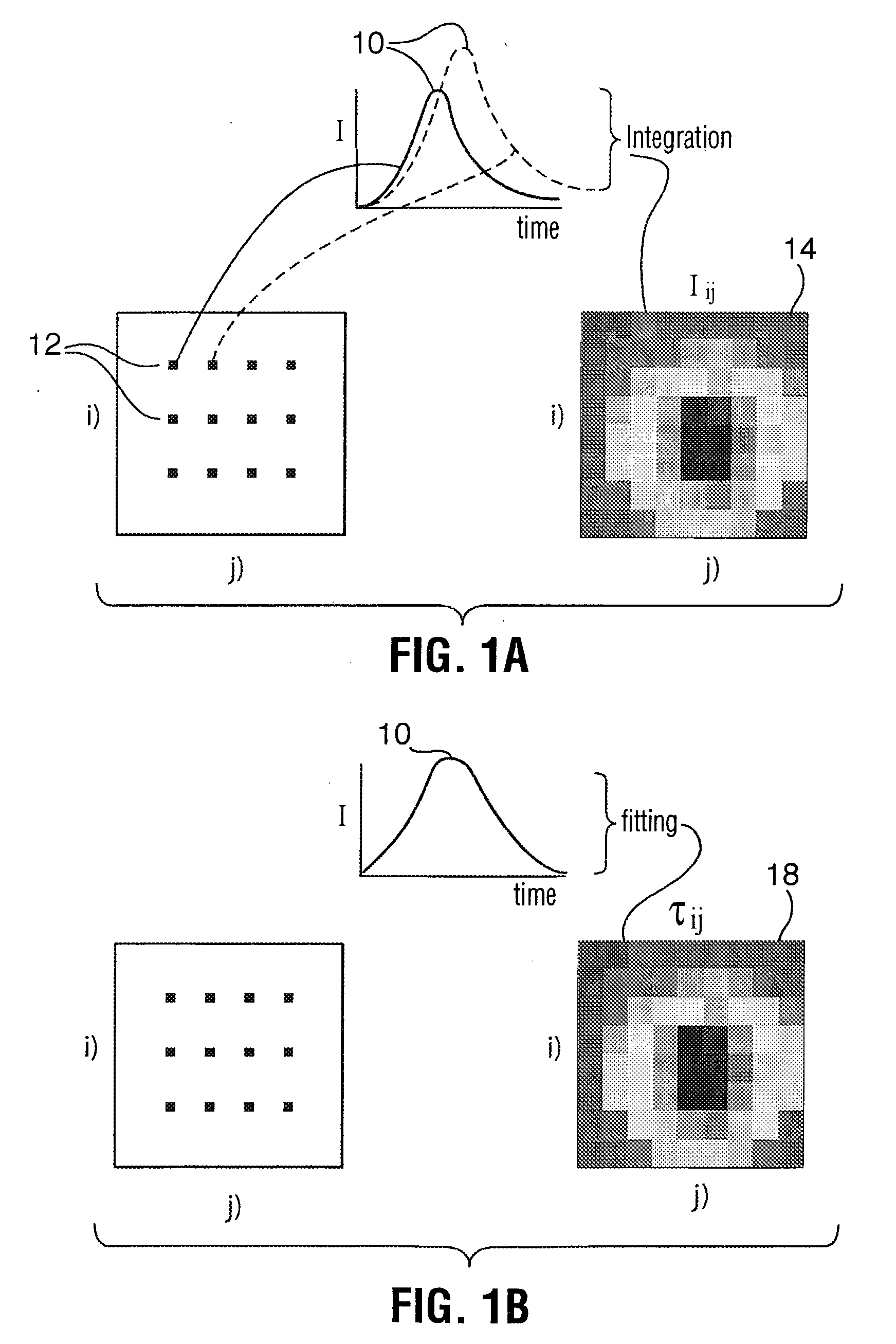
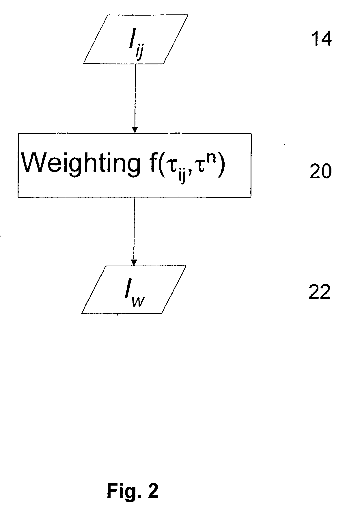
[0007] The present invention provides an improved method for enhancing contrast and specificity of fluorescence images of an object, such as a biological tissue, by selectively eliminating or reducing unwanted fluorescence from fluorophores other than the fluorophore of interest. The method is based on the generation of intensity images weighted as a function of measured lifetime in which the intensity information is conserved and hence information related to the concentration of the fluorophore of interest.
[0010] In yet a further embodiment, the method provides for a primary weighting step which can substantially reduce background fluorescence signal from intrinsic fluorophore species. Thus the fluorescence intensity signal can be multiplied by a primary weighting factor prior to the step of multiplying the fluorescence intensity by a weighting factor, the primary weighting factor being a function of the calculated fluorescence lifetime and two predetermined fluorescence lifetimes of two or more fluorophore species that are being imaged.

Problems solved by technology

However, the excitation and emission spectra of such extrinsic fluorophores often overlap with those of intrinsic fluorophores such that the fluorescence signal is a combination of the signals from each fluorophore.
As a result, fluorescence images often contain undesirable signals that obscure the signal from the fluorophore of interest.
All of them have limitations.
Methods based on fluorescence lifetime help distinguish signals from different fluorophores but do not retain the information related to fluorophore intensity and consequently information related to concentration of the fluorophore is lost.
Frequency domain hardware techniques require multiple image acquisition at a plurality of phase delays to suppress unwanted fluorescence and are therefore time consuming.

Method used


Image

  • Method for improving fluorescence image contrast
  • Method for improving fluorescence image contrast
  • Method for improving fluorescence image contrast

Examples


example 1

[0052] Equal volumes of 50 nM Cy5.5 and 150 nM Atto680 were mixed together. Fluorescence signal was obtained using eXplore Optix™ with a pulsed diode laser wavelength at 666 nm as the excitation light source. When the quantum yield, extinction coefficient, and fluorescence spectrum and filter window information are taken into account, the fluorescence signal ratio of Cy5.5 and Atto680 from the mixture is about 0.55:0.45.

[0053]FIG. 5 illustrates the method described above. Panel(a-i) is a raw fluorescence intensity image of the Cy 5.5 and Atto 680 mixture. A lifetime image (panel (a-ii)) was generated using an effective lifetime (fitting the TPSF with a single exponential). Panel (a-iii) exhibits a processed intensity image (Inew) obtained by performing a preliminary weighting on the raw intensity image. Because only Cy5.5 and Atto 680 are present there is no difference between the raw image and processed image (no background fluorescence). Panels(b-i) and (c-i) exhibit lifetime ima...

example 2

[0054] One hundred nM Cy5.5 and 200 nM Atto680 solution were arranged in two separate locations. Fluorescence signal was obtained using eXplore Optix with a pulsed diode laser wavelength at 666 nm as the excitation light source.

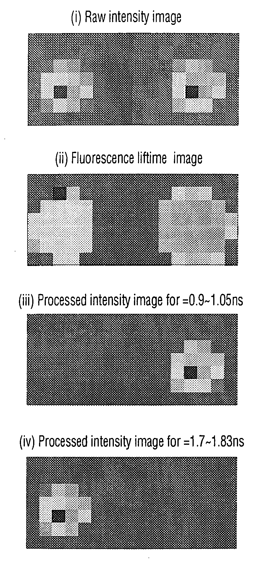
[0055] In the particular case where the location of fluorophore species within the object are not overlapping, there is no need for multi-exponential fitting of the TPSF and one can proceed directly with the weighting step of the method. FIG. 6 provides such an example in which the two fluorophores species do not overlap. Panel (i) of FIG. 6 is a measured raw fluorescence intensity image with two fluorophore species, Atto 680 on the left and Cy5.5 on the right. From the intensity image alone, without knowing a priori where the fluorophores are located, one would not be able to identify the fluorophores species. Panel (ii) is the corresponding fluorescence lifetime image obtained by fitting the TPSF of each pixel with a single exponential decay model. While t...

example 3

[0057] The fluorophore species may be the same fluorophore molecule in different environment. Thus, for example, the object may comprise one fluorophore having a lifetime τ1 when it is bound to a protein and a lifetime τ2 when it is free. In this case it is possible to model the TPSF by the following dual exponential:

f exp(−t / τ1)+(1−f)exp(−t / τ2)   (5)

[0058] where, t is the time, τ1 and τ2 are the respective lifetimes of the bound and free states and f is the fraction of fluorophores in the bound state: f=[bound] / ([bound]+[free]). The parameters in this model can then be obtained from measured data through multi-variate curve fitting. The dual exponential for free / bound fluorophore species can be used to obtain weighted intensity images as described above.


PUM


Abstract

There is provided an improved method for enhancing fluorescence images of an object, such as a biological tissue, by selectively eliminating or reducing unwanted fluorescence from fluorophores other than the fluorophore of interest. The method is based on the measurement of the lifetime of fluorophores while preserving information related to the fluorescence intensity of the fluorophore of interest.

Description

CROSS-REFERENCE TO RELATED APPLICATIONS [0001] This is the first application filed for the present invention. TECHNICAL FIELD [0002] The present invention relates to a method for reducing and / or eliminating unwanted fluorescence signals in optical images based on fluorescence lifetime of fluorophores. BACKGROUND OF THE INVENTION [0003] The monitoring of pharmacokinetics, genetic, cellular, molecular or other types of events in vivo is of great interest to monitor drug or gene therapy efficacy as well as disease status or progression in small laboratory mammals and in the human body. In this respect, fluorescence imaging, both in vitro and in vivo, has been used extensively to generate anatomical and functional information from within cells and organisms. [0004] Fluorescence imaging of internal parts of animals (including humans) for anatomical or functional purposes often involves the injection of an extrinsic fluorophore, typically chemically coupled with another molecule, that dis...

Claims


Application Information

Patent Timeline
IPC IPC(8): G06F19/00G06K9/00
CPCA61B5/0059G01N21/6408G06T2207/30024G06T5/008G06T2207/10064G01N21/6456G06T5/94
Inventor MA, GUOBIN
Owner ART RECH & TECH AVANCEES INC ART ADVANCED RES TECH INC
Learn More