
Flat plate panel solar electrical generators and methods

a technology of solar energy and electrical generators, applied in the direction of hybrid energy generation, pv power plants, thermal-pv power plants, etc., can solve the problems of inefficient electricity generation, difficult rotation, and high cost and strong support structure, and achieve the effect of increasing the conversion rate to electrical energy

Inactive Publication Date: 2006-07-13
LAWHEED PAUL
View PDF19 Cites 12 Cited by
  • Summary
  • Abstract
  • Description
  • Claims
  • Application Information

AI Technical Summary

Benefits of technology

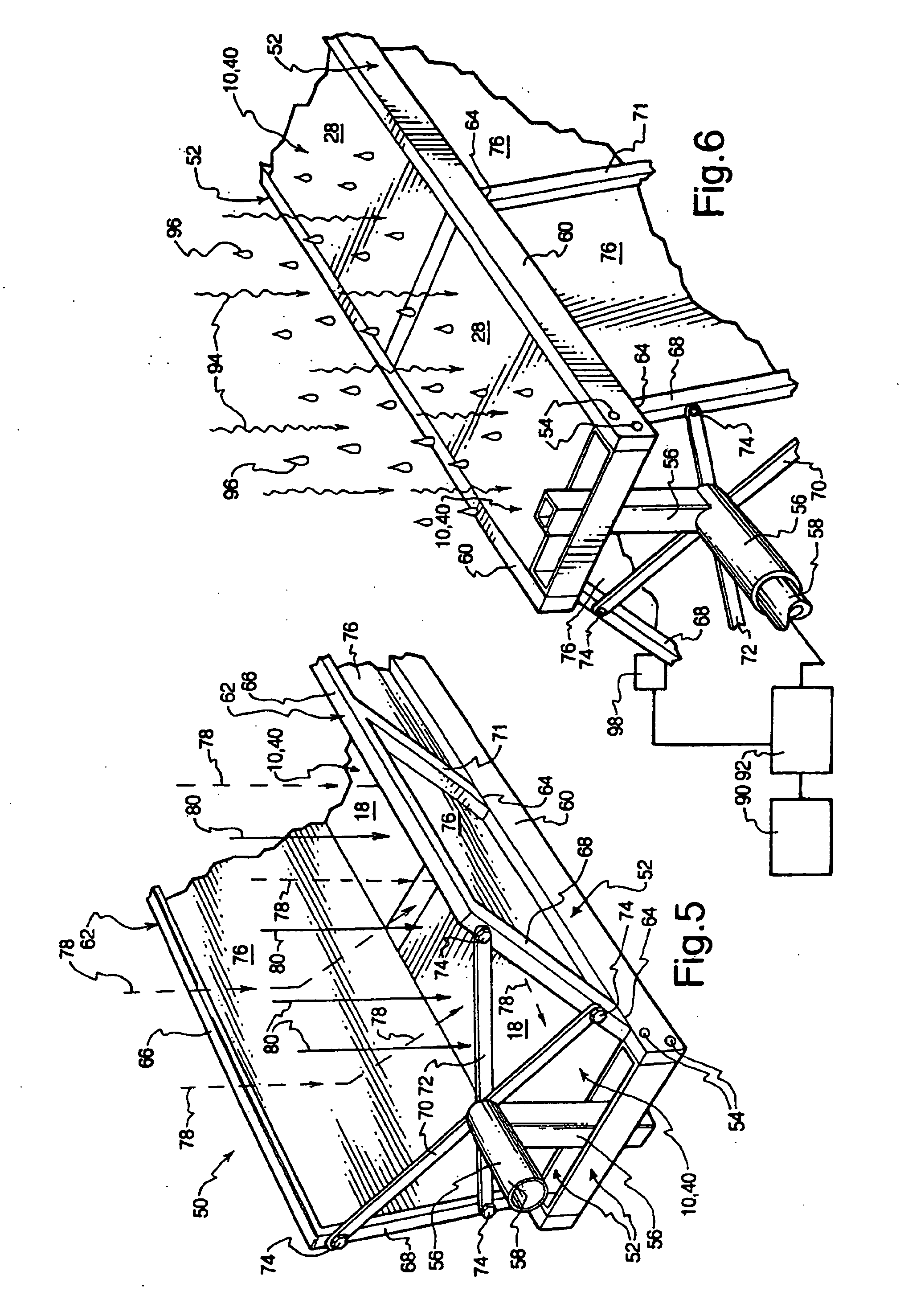
[0006] In brief summary, the present invention alleviates certain prior problems associated with flat plate panel generation of electricity from sunlight. The present invention, using low profile multiple axes tracking, keeps the surface of each flat plate panel upon which rays of the sun are impinged essentially perpendicular to those rays enabling a higher rate of conversion to electrical energy and a long interval each day during which conversion of sunlight to electricity is accommodated.
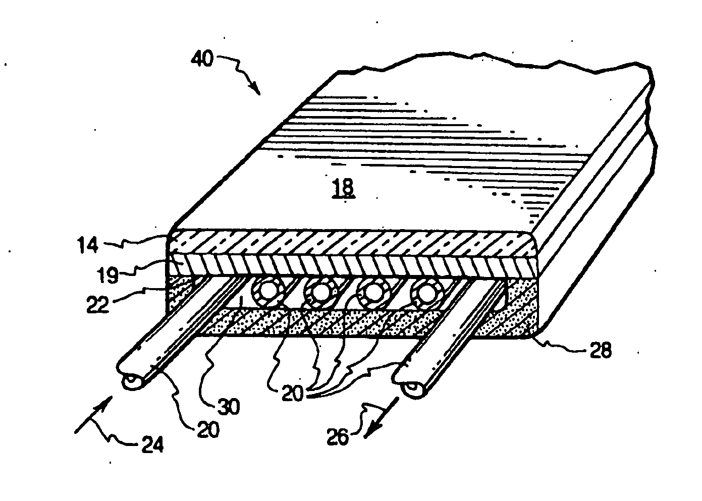
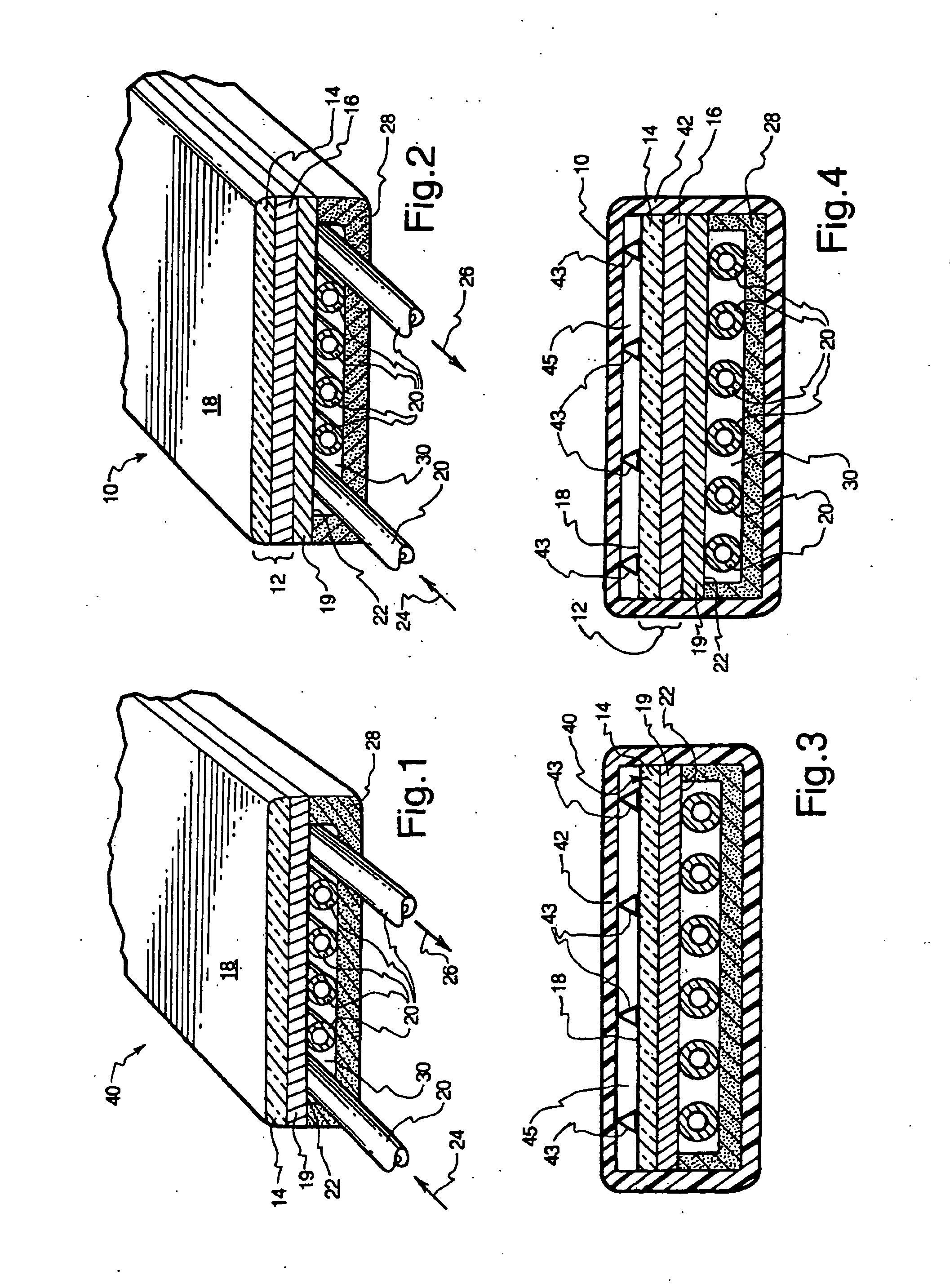
[0008] In addition, the efficiency of the solar elements of the flat plate panels is enlarged by uniquely cooling the flat plate panels using circulated fluid, whereby the thermal energy so obtained may be used to perform work to make the system more cost effective.
[0010] Another paramount object is to track the sun with one or more flat plate panel generators along a horizontal axis of rotation for the one or each row of flat plate panels so that the profile is low and the surface or face of each flat plate panel upon which rays of sunlight is impinged is kept essentially perpendicular to the rays, thereby eliminating defection loss of sunlight.

Problems solved by technology

This lack of perpendicularity results in inefficient generation of electricity because some of the sunlight is deflected off the impingement face of each flat plate panel.
While pedestal-based single or dual axis tracking of a large bank of flat plate panels, comprising a plurality of rows, around a single horizontal axis and a single vertical axis has been proposed, the resulting high vertical profile makes rotation awkward, requires expensive and strong support structure and subjects the panels and the support structure to high stress due to the weight of the assembly and large wind loads sometimes imposed thereon.
Damage results in significant expenses of repair and lack of productivity during downtime.
Further, the efficiency of the solar elements of prior art flat plate panels is low to begin with and the rate at which electricity is produced is farther reduced by reason of the high temperatures caused by the rays of the sun striking the flat plate panel and the process by which electricity is generated using solar cells.
This low efficiency is exacerbated by the high cost of commercially available solar cells.

Method used


Image

  • Flat plate panel solar electrical generators and methods
  • Flat plate panel solar electrical generators and methods
  • Flat plate panel solar electrical generators and methods

Examples


Embodiment Construction

[0023] This disclosure is of only some of many possible embodiments of the present invention and is directed broadly to the field of flat plate panel generation of electricity from solar energy. The embodiments of the invention, as depicted in the drawings, is concerned with obtaining a greater concentration of sunlight on flat plate panels to increase the amount of electricity so derived. The present invention, broadly, and as illustrated in the drawings, is also concerned with cooling of flat plate panels such that thermal energy so derived may be beneficially utilized thereby making flat plate panels more cost effective. The efficiency of flat plate panels, in accordance with the present invention, is further enhanced by utilizing a multiple axis tracking system whereby the face of each flat plate panel is maintained in a state of substantial perpendicularity to the rays of the sun thereby reducing the amount of lost solar energy heretofore angularly deflected off from the face o...


PUM


Abstract

Novel flat plate solar panels are disclosed, which, using low profile multiple axes tracking, keep the surface of each flat plate panel upon which rays of the sun are impinged essentially perpendicular to those rays enabling a higher rate of conversion to electrical energy and a long interval each day during which conversion of sunlight to electricity is accommodated. Side peripheral sunlight deflectors redirect rays of sunlight perpendicular to the face fo the flat plate panel but directly adjacent to and somewhat out of alignment with the impingement surface of the flat plate panels upon the impingement surfaces thereby concentrating a greater amount of sunlight to produce a greater quantity of electricity. A cooling system for the flat plate panels, using circulated fluid is disclosed whereby the thermal energy so obtained may be used to perform work to make the system more cost effective.

Description

CONTINUITY [0001] This application is a continuation of my co-pending U.S. patent application Ser. No. 10 / 616,200, filed Jul. 9, 2003, now ______, which is a continuation-in-part of my copending U.S. patent application Ser. No. 10 / 458,917, filed Jun. 10, 2003, which is a continuation of U.S. patent application Ser. No. 10 / 251,709, filed Sep. 21, 2002, now U.S. Pat. No. 6,696,637, which is a continuation of U.S. patent application Ser. No. 09 / 867,196 filed May 29, 2001, now U.S. Pat. No. 6,498,290.FIELD OF THE INVENTION [0002] The present invention relates generally to transformation of sunlight into electricity and, more particularly to improvements in flat plate panel solar electrical generators by which a greater magnitude of sunlight is perpendicularity concentrated on the flat plate panel to increase the amount of electricity derived therefrom and from which thermal energy is beneficially obtained. BACKGROUND [0003] Flat plate panel conversion of sunlight to electricity is well ...

Claims


Application Information

Patent Timeline
Patent Type & Authority Applications(United States)
IPC IPC(8): H01L31/042F24J2/54F24S23/30F24S23/74F24S50/20H01L31/052H01L31/058
CPCF24J2/085F24J2/14F24J2/38F24J2/54F24J2/542F24J2002/5468H01L31/0547Y02E10/43Y02E10/45Y02E10/47Y02E10/52H02S20/00H01L31/052F24S23/31F24S23/74F24S30/40F24S30/452F24S50/20F24S2030/136H01L31/0521H02S20/23H02S20/30H02S40/44Y02B10/10Y02E10/60Y02E10/40
Inventor LAWHEED, PAUL
Owner LAWHEED PAUL
Learn More