Blade holder, blade and blade tool head

a blade and tool head technology, applied in the direction of flat surface machines, solid separation, profiling/shaping machines, etc., can solve problems such as wood fibers or chips

Inactive Publication Date: 2006-07-13
LINDEX CHIPPING SYST
View PDF7 Cites 1 Cited by
  • Summary
  • Abstract
  • Description
  • Claims
  • Application Information

AI Technical Summary

Benefits of technology

[0008] This invention is based on the technical problem of providing a knife holder which can be assembled with chipping knives on the periphery and slabbing knives on the end face, a knife for this holder and a respective knife tool head which will jointly permit secure, self-centering holding of one chipping knife and one slabbing knife jointly on a holder without any play. This holder can in turn be secured on the tool head and allows relatively simple replacement of the knives without any complex adjustment work, whereby the chipping knife and the slabbing knife can also be mounted on the holder with the knives in close proximity even in the reground state if necessary.
[0010] The line of action of the holding force for the chopping knife as well as that of the slabbing knife are each in the angle range spanned by the contact faces inclined in a V shape, so that a self-centering effect of the two knives when secured on the knife holder is obtained due to the effect of the holding force. The centered position is unambiguously defined for each of the two knives by the pairs of cooperating contact faces inclined in a V shape and opposing one another with respect to the line of action of the holding force. The holding force which acts in this way also results in a uniform force distribution on these contact faces and thus on the whole in a favorable uniform fastening force acting on the respective knife and the knife holder. These characteristic properties of direct holding of the chipping knife and the slabbing knife on a common holder consequently ensure a secure mounting of the chipping knives and the slabbing knives on the tool head without any play even under load during chipping operation and thus permit a rapid and easy mounting of the knives with a high repeating accuracy of the knife position on insertion of a new knife without requiring complex adjustment work.
[0011] With the inventive knife holder as claimed in claim 2, the chopping knife and the slabbing knife are attached directly to the respective mounting face and the holding body is designed as a one-piece part and can in turn be attached directly to the knife tool head. Consequently, this permits very simple mounting of the chopping knife and the slabbing knife onto a joint one-piece holder body and dismantling it therefrom as well as mounting the holder body on and / or dismantling it from the knife tool head with direct fastening means without additional parts.
[0014] In a further refinement of this invention, holder fastening means for the knife holders are provided laterally next to the mounting faces for the knives. In this way the holders can be mounted on the tool head without being hindered by the knives and dismantled from it again without having to remove the knives from the holder.
[0015] Another embodiment of the inventive knife is designed so that it has one or two inclined contact areas on at least one transverse side, these contact areas extending from one end of the knife cutting edge with a slope that corresponds to a corresponding inclined angle of the relative position of the peripheral knives and the slabbing knives on the holder, so that when the knife is mounted on the holder as a chipping knife or as a slabbing knife, it is in contact with the other knife not only with spot contact but instead with linear or area contact with this area. The chipping knife and slabbing knife may be provided with the corresponding slopes or the slope may be provided completely on one knife, in which case the other knife then has a transverse edge perpendicular to the knife cutting edge. The linear or surface abutment of the two knives in an area in contact with the active cutting edges yields the advantageous effect that the two knives are always in mutual contact without any essential gap on their active knife cutting edges even in a used, reground state, so that there is no unwanted clogging or jamming of chipped material between the two knives in the meantime.
[0017] In a further refinement of this invention, multiple second knife holders are provided on the lateral surface of the base body of the tool head in the form of a truncated cone behind said inventive knife holders, each being assembled with a chipping knife and a slabbing knife, and are offset with respect to these in the circumferential direction, whereby the second knife holder is assembled with only one chipping knife. It is found that the knife tool head designed in this way fulfills very well the cutting function as well as the smoothing function.

Problems solved by technology

Due to wear and in particular due to regrinding of the knife cutting edges, the case may therefore occur when the point contact of the active knife cutting edges of the chipping knife and the slabbing knife are lost, the result being a continuous gap between the chipping knife and the slabbing knife, which can become clogged with wood fibers or chips in an undesirable manner during operation.

Method used


Image

  • Blade holder, blade and blade tool head
  • Blade holder, blade and blade tool head
  • Blade holder, blade and blade tool head

Examples


Embodiment Construction

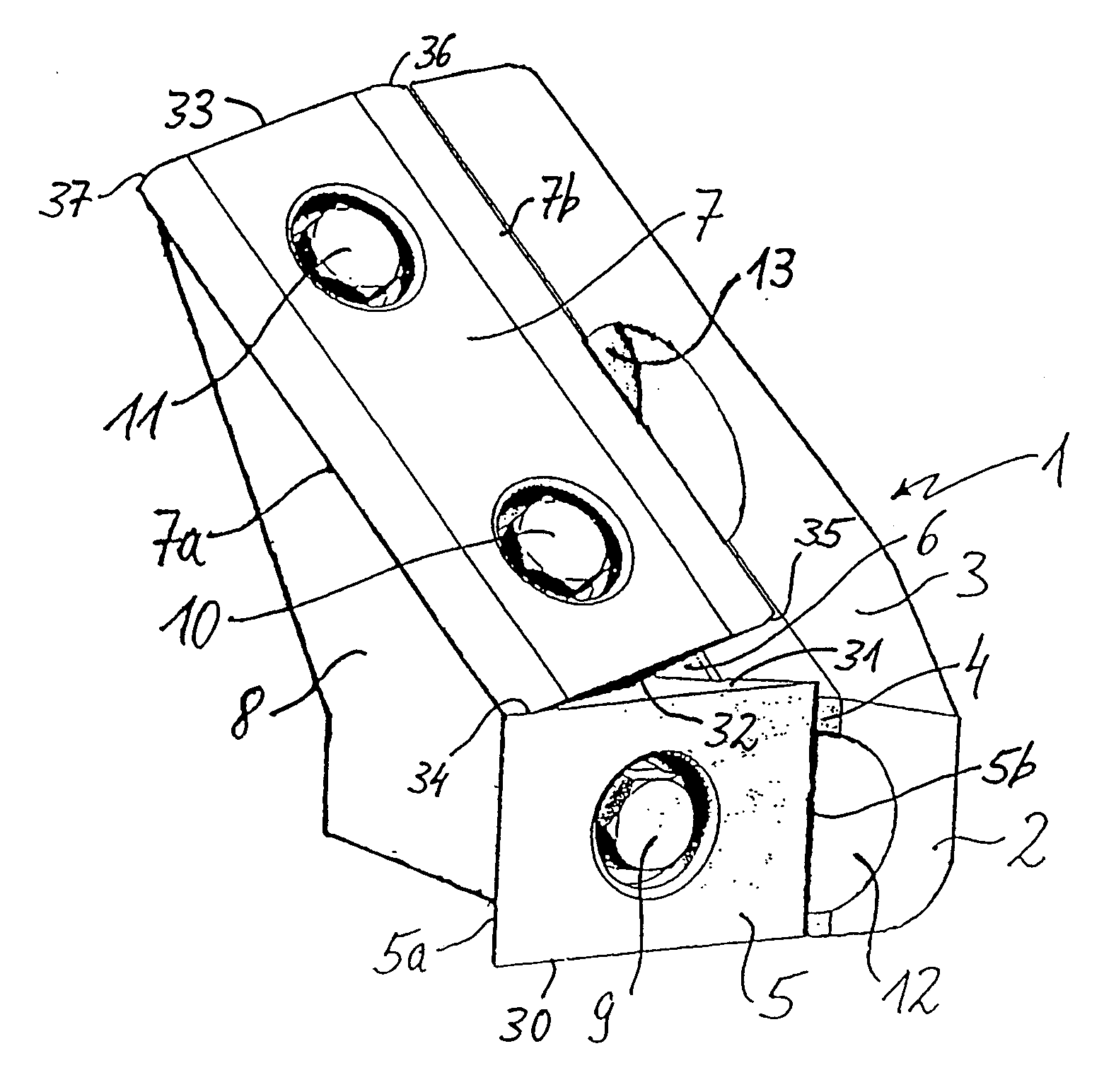
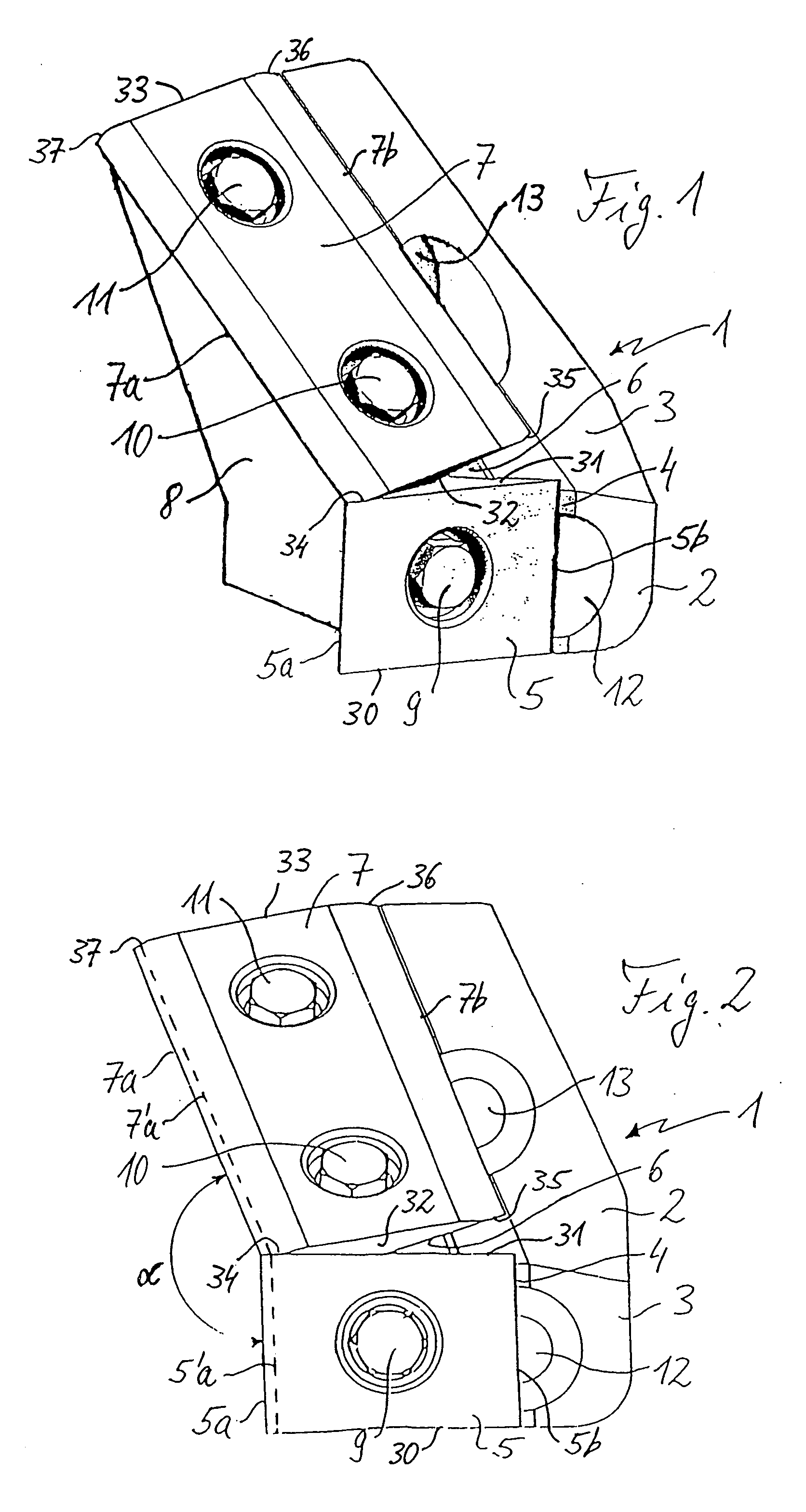
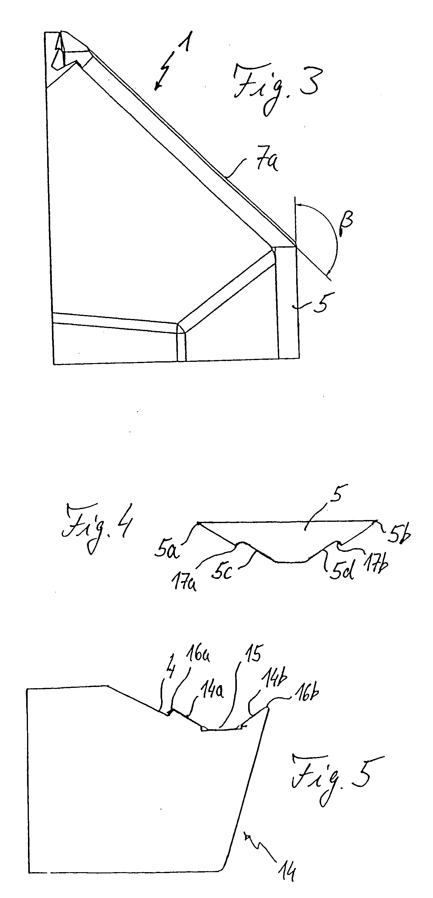
[0032]FIGS. 1 through 3 show a knife holder for a counterclockwise knife tool head. The knife holder consists of a one-part solid metal holder body 1 having the shape indicated in FIGS. 1 through 3. The forward holder body face in FIGS. 1 and 2 includes a smaller first face area 2 and a larger second face area 3 which is inclined with respect to the former. A left part (in FIGS. 1 and 2) of the first face area 2 is designed as a mounting face 4 on which a slabbing knife 5 is mounted. A left part (in FIGS. 1 and 2) of the second face area 3 is designed as a mounting face 6, which is in contact with the mounting face 4 and on which a chipping knife 7 is mounted.

[0033] Turning knives each with two opposing cutting edges 5a, 5b and / or 7a, 7b are used as the slabbing knives and chipping knives 5, 7, whereby the slabbing knife 5 has a rectangular base shape with transverse sides 30, 31 perpendicular to the longitudinal-side knife cutting edges 5a, 5b and positioned on the holder body 1 s...


PUM


Abstract

A blade, blade holder, and blade tool head, is provided. The blade holder comprises a mounting surface for a cleaver and an adjacent inclined mounting surface for a flat blade and blade fixing elements for detachably fixing the blades to their mounting surfaces. The blade mounting surfaces have holder contact surfaces with a V-shaped cross-section, and the blade fixing elements directly fix the blades, each of which has corresponding inclined V-shape contact surfaces, to their respective mounting surface, with a retaining force that acts between the inclined V-shaped contact surfaces. The blade has on its lateral side an oblique bearing region, which permits both blades to lie flat against one another.

Description

[0001] This is a National Phase Application based on PCT / EP2003 / 010000, filed Sep. 9, 2004 and claims the priority of German Application 102 42 336.9, filed Sep. 9, 2002 the disclosure of which is expressly incorporated by reference herein.BACKGROUND AND SUMMARY OF THE INVENTION [0002] This invention relates to a knife holder for a knife tool head that can be assembled with chipping knives on the periphery and slabbing knives on the ends, where the knife holder has a mounting face for a chipping knife and an adjacent mounting face inclined to the former for a slabbing knife and knife mounting means for detachable mounting of the chipping knife and the slabbing knife on the respective mounting face; this invention also relates to a respective knife and a knife tool head having a base body in the form of a truncated cone or a cylinder and multiple knife holders attached thereto with one or more knives mounted on each. [0003] Such knife tool heads are used, for example, for chipping wo...

Claims


Application Information

Patent Timeline
Patent Type & Authority Applications(United States)
IPC IPC(8): B02C17/02B27C1/00B07B13/00B26D1/12B27L11/00B27G13/08
CPCB27L11/005B27L11/007Y10T407/1948Y10T407/1908Y10T407/1932
Inventor GUELS, MARTIN
Owner LINDEX CHIPPING SYST
Why Eureka
Try Eureka