Phase-change heat reservoir device for transient thermal management

Inactive Publication Date: 2006-07-13
ENERTRON
View PDF17 Cites 48 Cited by
  • Summary
  • Abstract
  • Description
  • Claims
  • Application Information

AI Technical Summary

Benefits of technology

[0010] Systems and methods in accordance with the present invention overcome the prior art by providing a heat transfer system capable of managing thermal transients, thus giving engineers greater flexibility in designing thermal solutions for applications subject to transient heat-generation. In accordance with one embodimen

Problems solved by technology

Recent advances in the design and fabrication of electronic components has dramatically increased their speed and density but has, at the same time, led to significant challenges for thermal engineers seeking to provide heat-transfer solutions for such components.
These heat transfer challenges are particularly severe in applications subject to transient heat generation.
Currently known methods of addressing transient heat generation are undesirable in a number of respects.
This “worst-case-scenario” practice invariably results in an unnecessarily large heat sink or cooler that is not used to its full capacity during normal operation.
Furthermore, if there is a space c

Method used


Image

  • Phase-change heat reservoir device for transient thermal management
  • Phase-change heat reservoir device for transient thermal management
  • Phase-change heat reservoir device for transient thermal management

Examples


Embodiment Construction

[0023] Systems and methods in accordance with the present invention overcome the prior art by providing a heat transfer system capable of managing thermal transients through the use of a phase change heat reservoir device.

[0024] Overview

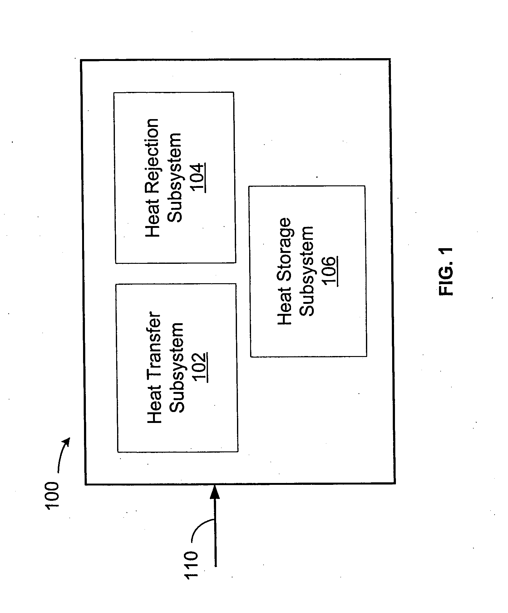
[0025] Referring now to FIG. 1, a system 100 in accordance with the present invention generally includes a heat transfer subsystem 102, a heat rejection subsystem 104, and a heat storage subsystem 106, wherein system 100 accepts a heat input 110 subject to transient conditions. Heat storage subsystem 106 is configured to absorb excess thermal load generated during these transient conditions, and heat rejection subsystem 104 is configured to transfer the heat away from system 100 (i.e., to the ambient environment). Heat transfer subsystem 102 then provides the thermal path between the various subsystems 106 and 104 and heat input 110. As will be discussed in detail below, these three subsystems may comprise a variety of components, and may be arrang...


PUM


Abstract

A heat transfer system is presented for managing thermal transients, thus providing engineers greater flexibility in designing thermal solutions for applications subject to transient heat-generation. A heat reservoir device for managing a heat input subject to transient conditions includes a heat transfer subsystem having a first end and a second end, where the first end is thermally coupled to the heat input; a heat storage subsystem coupled to the second end of the heat transfer subsystem, where the heat storage subsystem comprises a phase change material responsive to the transient conditions. The excess heat load during transient operation is temporarily absorbed by the latent heat of fusion when the phase change material changes its phase from solid to liquid. Subsequently, the absorbed heat can be released back to the ambient via a heat rejection subsystem. This allows engineers to design smaller heat sinks capable of accommodating given transient conditions. This results in heat sinks which are lower cost and smaller size, or which reduce the requirement to provide higher airflow, thereby also decreasing cost and noise, and increasing reliability.

Description

CROSS-REFERENCE TO RELATED APPLICATIONS [0001] This application is a continuation of U.S. patent application Ser. No. 10 / 055,434, filed Jan. 23, 2002, which claims priority from U.S. Provisional Patent Application S / N 60 / 261,551, filed Jan. 26, 2001.BACKGROUND OF THE INVENTION [0002] 1. Technical Field [0003] The present invention relates, generally, to heat transfer systems and, more particularly, to a method of managing thermal transients through the use of phase-change heat reservoirs. [0004] 2. Background Information [0005] Recent advances in the design and fabrication of electronic components has dramatically increased their speed and density but has, at the same time, led to significant challenges for thermal engineers seeking to provide heat-transfer solutions for such components. These heat transfer challenges are particularly severe in applications subject to transient heat generation. [0006] Currently known methods of addressing transient heat generation are undesirable in...

Claims


Application Information

Patent Timeline
IPC IPC(8): F28D19/00H05K7/20
CPCF28D15/02F28D20/021H01L23/427Y02E60/145H01L2924/0002H01L2924/00Y02E60/14
Inventor CHOU, DER JEOUNELSON, DANIEL TODD
Owner ENERTRON
Why Eureka
Try Eureka