
Automated method of and system for dimensioning objects over a conveyor belt structure by applying contouring tracing, vertice detection, corner point detection, and corner point reduction methods to two-dimensional range data maps of the space above the conveyor belt captured by an amplitude modulated laser scanning beam
a laser scanning and automatic technology, applied in the field of automatic tunnel type laser scanning package identification and measuring system, can solve the problems of inability to scan bar code systems in a true omni-directional sense, and the inability to achieve true omni-directional scanning along the principal planes of a large 3-d scanning volume,
Patent Information
- Authority / Receiving Office
- US · United States
- Patent Type
- Applications(United States)
- Current Assignee / Owner
- Publication Date
- 2006-07-13
- Estimated Expiration
- Not applicable · inactive patent
Smart Images
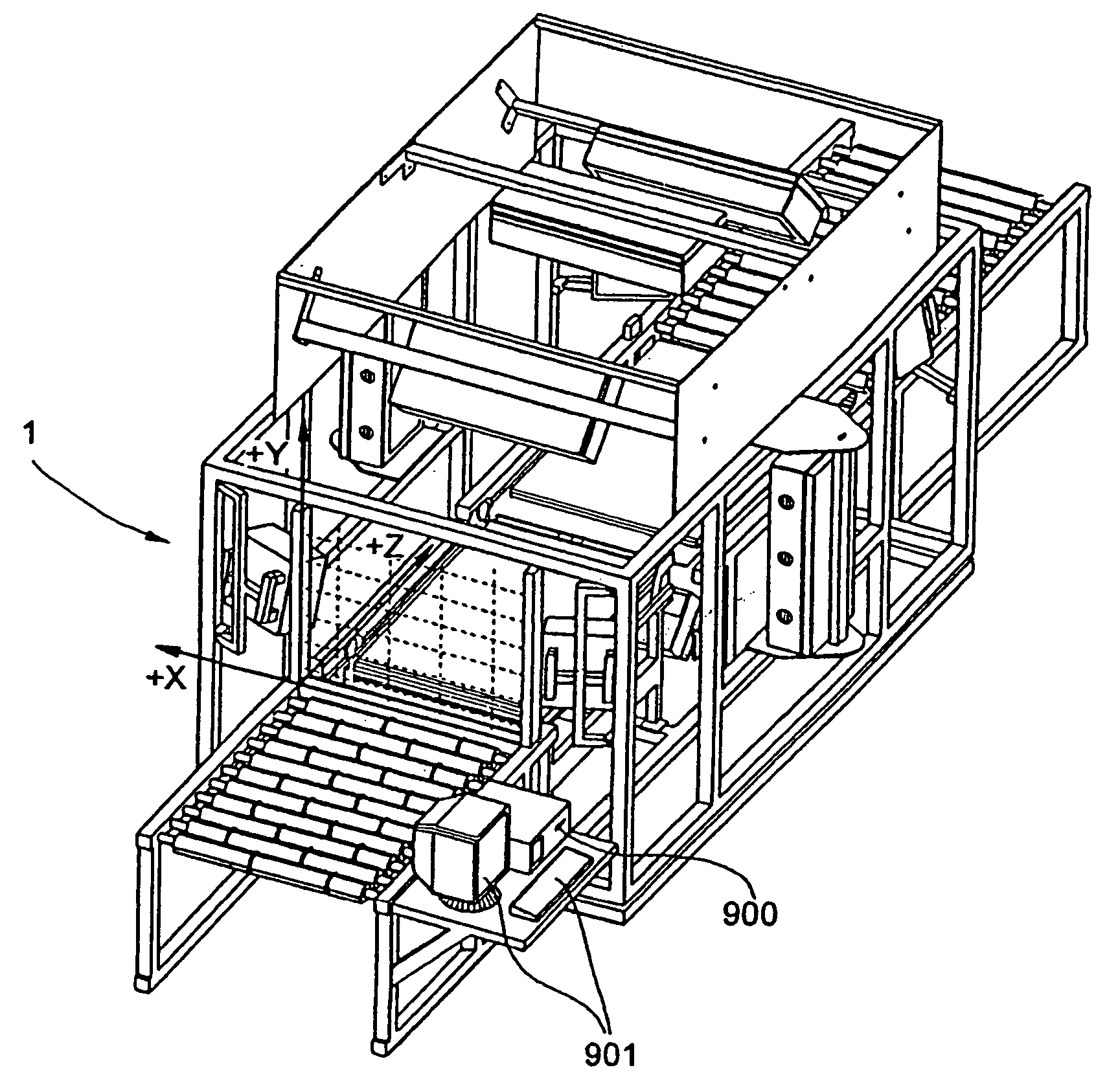
Figure 1 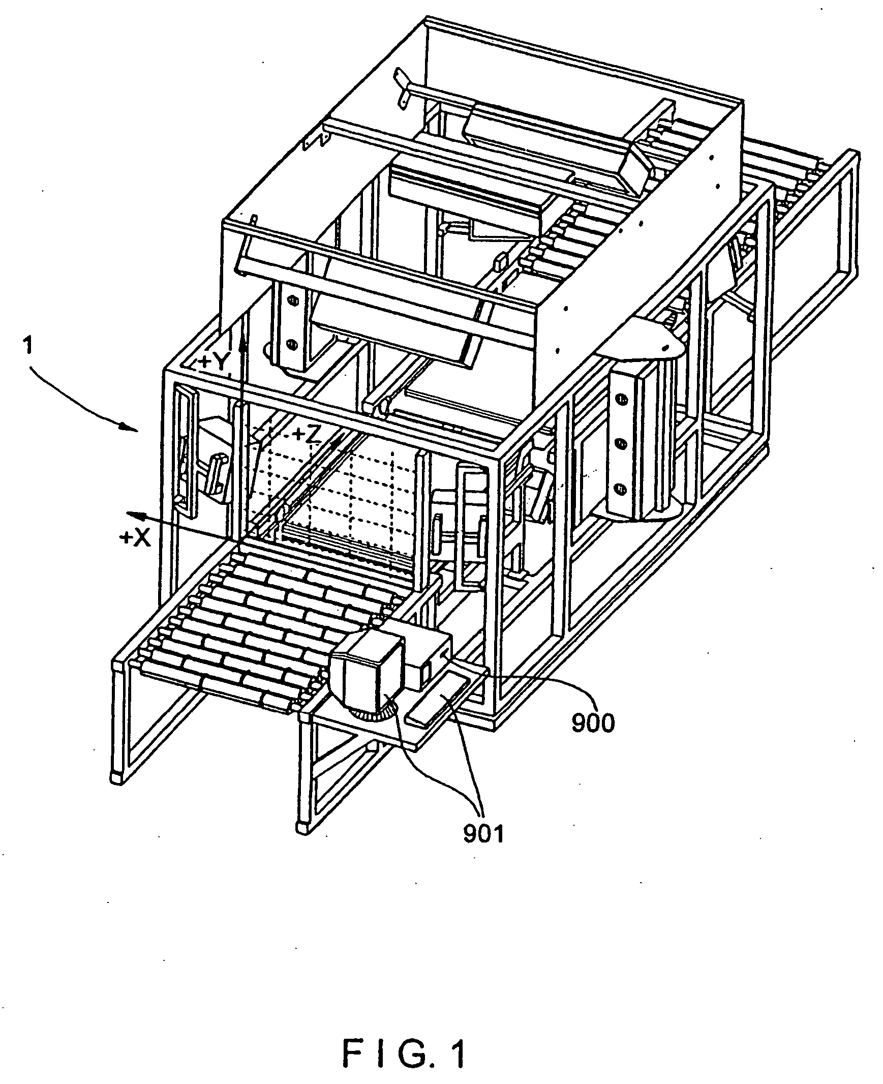
Figure 2 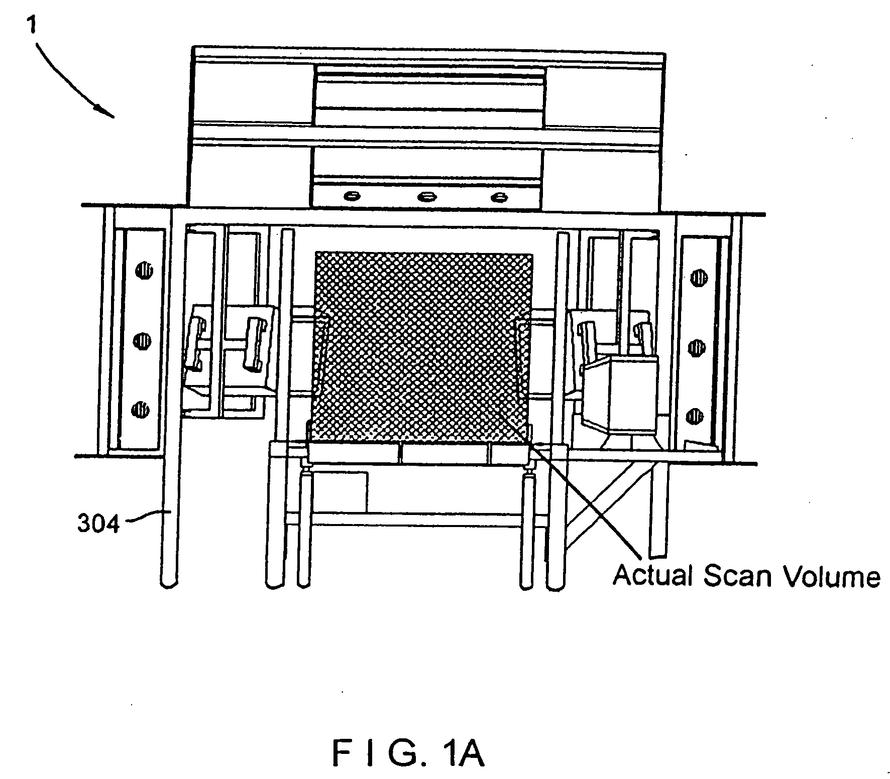
Figure 3
Abstract
Description
CROSS-REFERENCE TO RELATED US APPLICATIONS
[0001] This is a Continuation of application Ser. No. 10 / 038,727 filed Jan. 2, 2002 which Application is related to the following U.S. patent application Ser. No. 09 / 667,190 filed Sep. 21, 2000, now U.S. Pat. No. 6,705,526; Ser. No. 09 / 327,756 filed Jun. 7, 1999, now abandoned: application Ser. No. 09 / 305,986 filed May 5, 1999, now U.S. Pat. No. 6,619,550; application Ser. No. 09 / 275,518 filed Mar. 24, 1999, now U.S. Pat. No. 6,457,642; application Ser. No. 09 / 274,265 filed Mar. 22, 1999, now U.S. Pat. No. 6,382,515; Ser. No. 09 / 243,078 filed Feb. 2, 1999, now U.S. Pat. No. 6,354,505; Ser. No. 09 / 241,930 filed Feb. 2, 1999, now U.S. Pat. No. 6,422,467; Ser. No. 09 / 157,778 filed Sep. 21, 1998, now U.S. Pat. No. 6,517,004; Ser. No. 09 / 047,146 filed Mar. 24, 1998, now U.S. Pat. No. 6,360,947; Ser. No. 08 / 949,915 filed Oct. 14, 1997, now U.S. Pat. No. 6,158,659; Ser. No. 08 / 854,832 filed May 12, 1997, U.S. Pat. No. 6,085,978; Ser. No. 08 / 886,80...
Examples
embodiment 1
[0310] As shown in FIGS. 1 through 1E, the tunnel scanning system of the first illustrative embodiment 1 comprises an arrangement of laser scanning subsystems (i.e. scanners) which, by virtue of their placement, relative to the conveyor belt subsystem 300, essentially form a “tunnel” scanning subsystem over and about the conveyor belt of the conveyor subsystem 300. In the field of package sortation of any sort, whether it be mail, luggage (as in an airport terminal) or other items or boxes, this type of code symbol scanning system is known as a “tunnel scanning system” by those skilled in the art.
[0311] The tunnel scanning system of the first illustrative embodiment, shown in great detail in FIGS. 1 through 32B, can be designed and constructed to meet any specific set of customer-defined scanning parameters. For example, in the first illustrative embodiment, the bar code label can be on any one side of a box having six or more sides. The bar code label could be in any orientation. F...
embodiment 2000
[0463] Referring now to FIGS. 33 through 34, the “dual-lane” automated tunnel-type laser scanning system of the second illustrated embodiment 2000 will now be described in detail. As in the first illustrative embodiment depicted in FIGS. 1 through 32B, the system of the second illustrative embodiment is designed to identify and measure packages that are singulated along a conveyor subsystem in a conventional manner.
Overview of the Tunnel Scanning System of the Second Illustrative Embodiment of the Present Invention
[0464] As shown in FIGS. 33 and 34, the automated tunnel scanning system of the second illustrative embodiment indicated by reference numeral 2000 comprises an integration of subsystems, namely: a high-speed package conveyor system 2100 having a conveyor belt 2101 having a width of at least 60 inches to support a pair of package transport lanes along the conveyor belt; a first pair of triple-disc holographic laser scanning bar code symbol reading subsystems 2200A and 220...
first embodiment
[0503] Notably, the holographic LADAR-based imaging and dimensioning systems 3301B described above, without modification, can also function as compact single-line, laser scanner having very large depth of field, reduced optical throw, and laser scan lines with minimum curvature (i.e. minimum bow). The single line scanner uses a holographic disk to create a sequence of scan lines that all leave the disk at the same diffraction angle but have different focal lengths. In this scanner described above, the resulting linear scan pattern has six focal planes, providing a very large depth of field for high density bar codes. As mentioned above, six different holographic facets for the six focal planes are spatially repeated three times around the disk for a total of eighteen facets on the scanning disk. This replication of the basic scan pattern results in a high speed scanner.