Apparatus and method for capacitive measurement of materials

a capacitive measurement and apparatus technology, applied in the direction of electrical/magnetic thickness measurement, magnetic property measurement, instruments, etc., can solve the problem of not meeting the characteristic of measuring methods, the need of a metallic support, and the contact of the ball with the object to be measured, so as to increase the accuracy of thickness measurement

Inactive Publication Date: 2006-07-13
PLAST CONTROL GMBH
View PDF19 Cites 31 Cited by
  • Summary
  • Abstract
  • Description
  • Claims
  • Application Information

AI Technical Summary

Benefits of technology

[0015] Preferably, the measuring head has a supply opening for gas or air for creating a gas or air cushion between the measuring head and the film. Such an air cushion results in a certain self-regulation of the distance between the measuring head and the film.
[0016] Preferably, at least one sensor optical system of the distance measuring device is integrated into the measuring head. When the distance measuring device is arranged close to the thickness measuring device, this has the advantage that the distance is measured directly in the vicinity of the location of the thickness measurement and thus contributes to an increased accuracy of the thickness measurement.
[0017] In a particularly preferred embodiment, the optical distance measurement is a chromatic distance measurement. This requires only a single detection aperture at the measuring head. The chromatic distance measurement is performed for example with white light and an optical system which focuses the different wavelengths of the light at different distances from the detection aperture. It is a particular advantage of the chromatic distance measurement that it is robust against bulging or curvature of the film surface and permits for example an angular displacement of up to ±30i. In addition, it is insensitive against rills or streaks on the film, roughness of the film, and the speed of advance of the film.
[0018] The measuring head preferably provides a detection space for the optical distance measuring device, which detection space is situated on the rear side of the detection aperture and includes a device for supplying gas or air for scavenging the detection aperture. As a result, the detection space of the optical distance measuring device, which is open towards the detection aperture, may for example be held at a slightly increased pressure in relation to the area in front of the measuring head, so that no contaminants will enter through the detection aperture.

Problems solved by technology

Measurement methods are known, which do not fulfill this feature.
Disadvantageous is on the one hand the necessity of a metallic support and, on the other hand, the contact of the ball with the object to be measured.
Disadvantageous is in any case the necessity of a metallic support roller.
Here, it is a disadvantage that a triangulation sensor is necessary on both sides of the material.
Again, it is particularly the necessity of a support which is disadvantageous.
Moreover, the accuracy of the measurement is limited, due to fluctuations in the thickness of the air cushion.
A problem is that a change in the distance between the film and the capacitive measurement device tampers the capacitance measurement and, consequently, the thickness measurement, wherein the measurement error may be of the same order of magnitude as the measured film thickness.
This disturbing influence of distance changes becomes larger with increasing distance between the measuring head and the film, since the field strength of the capacitor decreases strongly at larger distances.
In the production of blow films, however, the movements of the film inevitably lead to fluctuations in the distance between the measuring head and the film.
These fluctuations disturb the capacitive measurement and lead to erroneous measurement results
This measuring head has the drawback that, on the one hand, it is required that the capacitive thickness measurement shall be as insensitive as possible to the distance within the available distance range.
On the other hand, the frictionless suspension of the measuring head is very complex.
Moreover, the sensor head will not always follow-up to the film with sufficiently quick response, because of its mass of inertia, so that the admissible distance range may be left.
A drawback is high effort for the pressure measurement, which, moreover, permits to derive the distance between the measuring head and the film only indirectly and with a low reliability and depends on the advance speed, the curvature and the surface properties of the film.
The position adjustment of the measuring head influences the pressure in the air cushion only indirectly and with time delay and, moreover, the mass of inertia of the measuring head makes it difficult to adjust the position of the measuring head quickly and exactly.
Under certain operating conditions of a blow film apparatus, it may therefore not be possible to stably maintain the target reference pressure.

Method used


Image

  • Apparatus and method for capacitive measurement of materials
  • Apparatus and method for capacitive measurement of materials
  • Apparatus and method for capacitive measurement of materials

Examples


Embodiment Construction

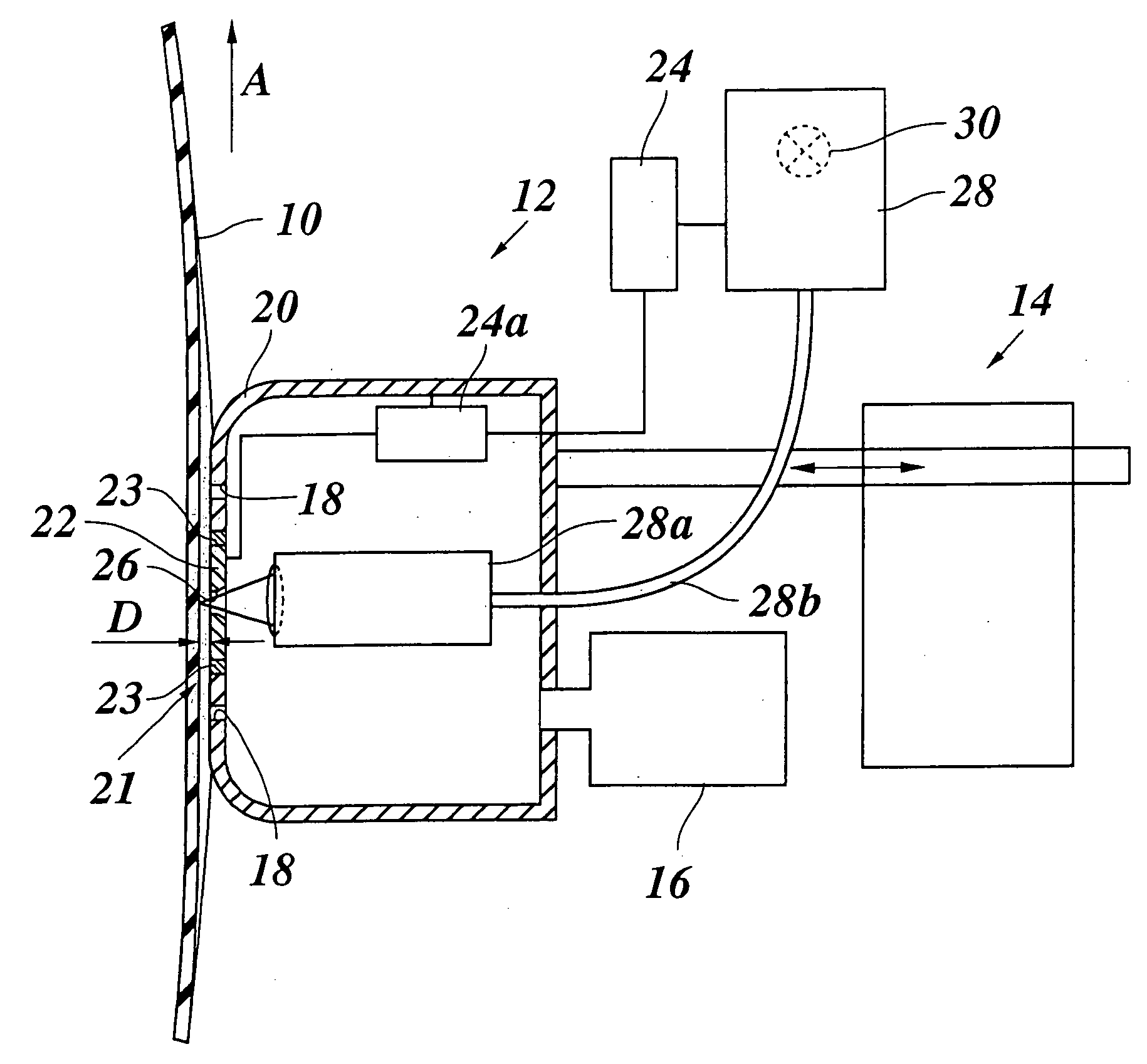
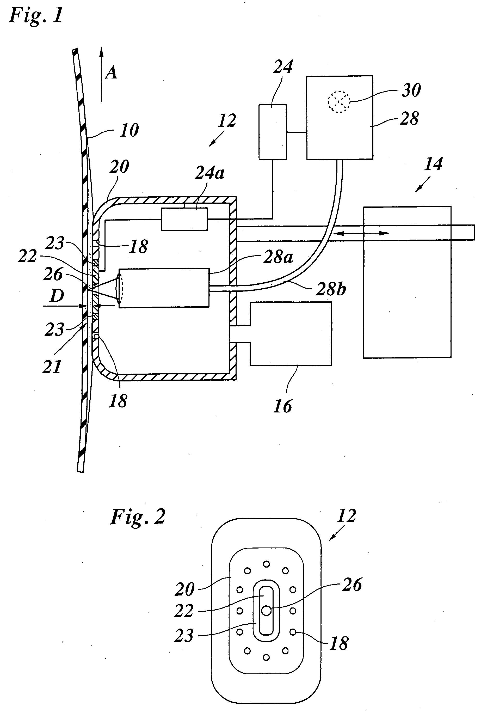
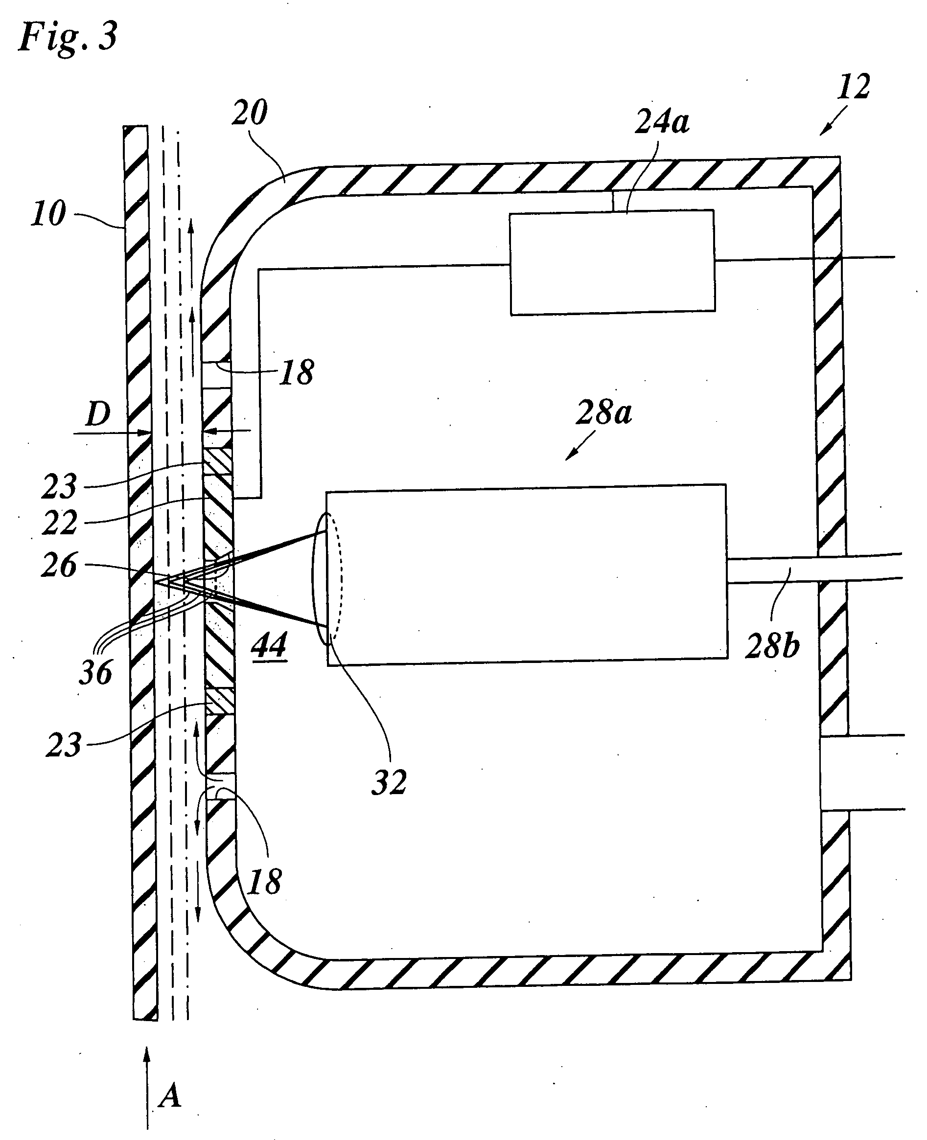
[0025]FIG. 1 shows, in a vertical section, a portion of a tube-like film 10 which is extruded from an extrusion die, is inflated by internal air to form a film bubble and is drawn-off in a direction indicated by an arrow A. For measuring the thickness of the film 10, a measuring head 12 is provided, which is rounded at its front side facing the film 10, in order to prevent the film 10 from being damaged.

[0026] During the measurement, the measuring head 12 is held in front of the film 10 by means of a positioning device 14, and a compressed air generator 16 generates compressed air which exits via supply openings 18 at the front side of the hollow measuring head 12 and causes an air cushion to build up between the measuring head 12 and the film 10. By means of the positioning device 14, the measuring head 12 is held in a position in which it slightly deflects the film 10 with the air cushion. Then, the internal pressure of the film bubble assures that the film 10 passes essentially ...


PUM

PropertyMeasurementUnit
diameteraaaaaaaaaa
thicknessesaaaaaaaaaa
optical distance measuringaaaaaaaaaa

Abstract

Method for measuring thicknesses of a film, a foil or a material layer with a measuring head which is spaced away from the film and with which a capacitive thickness measurement is performed, in which an optical distance measurement is performed with a distance measuring device and a distance determined by the optical distance measurement is used in determining the film thickness in the capacitive thickness measurement.

Description

BACKGROUND OF THE INVENTION [0001] The invention relates to an apparatus and a method for measuring the thickness of a foil, a film or a material layer by means of a measuring head which is spaced away from the film and with which a capacitive thickness measurement is performed. [0002] Methods of measuring film thickness are used in particular in the production of plastic films, so that the film thickness and, as the case may be, the evenness of the film thickness over the width of the film may be monitored during the manufacturing process and may be regulated, if necessary. For example, in a blow film apparatus, the measuring head is arranged at the film bubble, which is inflated by internal blow air and is drawn-off upwardly, in such a manner that it may revolve around the film bubble and thus can measure the film thickness on the entire periphery of the film bubble during one revolution. As it would be difficult, in particular in case of blow films, to arrange components of the m...

Claims


Application Information

Patent Timeline
Patent Type & Authority Applications(United States)
IPC IPC(8): G01R27/26G01N21/00
CPCG01B7/06G01B7/08G01B7/087G01B2210/50
Inventor KONERMANN, STEFANSTEIN, MARKUS
Owner PLAST CONTROL GMBH
Why Eureka
Try Eureka