Wavefront sensor having multi-power beam modes, independent adjustment camera, and accommodation range measurement

a wavefront sensor and beam mode technology, applied in the field of ophthalmic wavefront aberration diagnostic tools, can solve problems such as damage to the retina, and achieve the effect of improving the initial focus and precision of light, and improving the wavefront sensor

Inactive Publication Date: 2006-07-13
BARCLAYS BANK PLC AS SUCCESSOR AGENT
View PDF19 Cites 19 Cited by
  • Summary
  • Abstract
  • Description
  • Claims
  • Application Information

AI Technical Summary

Benefits of technology

[0010] According to the invention, a wavefront sensor can be improved by enhancing the initial focus and precision of light impinging on the retina of an eye, which aids in focusing on a sensor a group of imaged light spots that can be used to determine the higher order aberrations of the eye, generally referred to as monochromatic aberrations represented by third and higher order Zernike orders and typically excluding defocus and astigmatism. Specifically, a wavefront sensor is implemented in one embodiment with an adjustment camera independent of a lenslet camera. A laser is placed into a lower power mode and projects the light onto the retina. The light is brought into focus with the help of the adjustment camera. Because the light entering the adjustment camera that is backscattered or reflected from the retina is not divided by a lenslet array, the intensity of that light is not reduced as it would be for such a lenslet array. A control system can employ data of the light on the retina from the adjustment camera to more precisely focus the imaged spots onto the sensor using “trombone”-type focusing optics.
[0011] Once the adjustment camera has been used to initially focus the laser onto the retina, the laser is briefly brought to a higher power mode, which if left on indefinitely could damage the retina, but is only flashed for an instant. The image returned in this high power mode is then provided through the lenslet array. Although the lenslet array divides the returned light into a plurality of spots, the high power improves the signal intensity and contrast of each of those spots.
[0012] The size of the lenslet array may thus be reduced, for example, from an 800-micron center-to-center distance for the lenslets with an 80-millimeter focal length to a 400-micron center-to-center distance with a 40-millimeter focal length. This allows either a smaller footprint for the device or a greater number of lenslets and a correspondingly greater number of image points, corresponding to higher resolution of the system.

Problems solved by technology

Once the adjustment camera has been used to initially focus the laser onto the retina, the laser is briefly brought to a higher power mode, which if left on indefinitely could damage the retina, but is only flashed for an instant.

Method used


Image

  • Wavefront sensor having multi-power beam modes, independent adjustment camera, and accommodation range measurement
  • Wavefront sensor having multi-power beam modes, independent adjustment camera, and accommodation range measurement
  • Wavefront sensor having multi-power beam modes, independent adjustment camera, and accommodation range measurement

Examples


Embodiment Construction

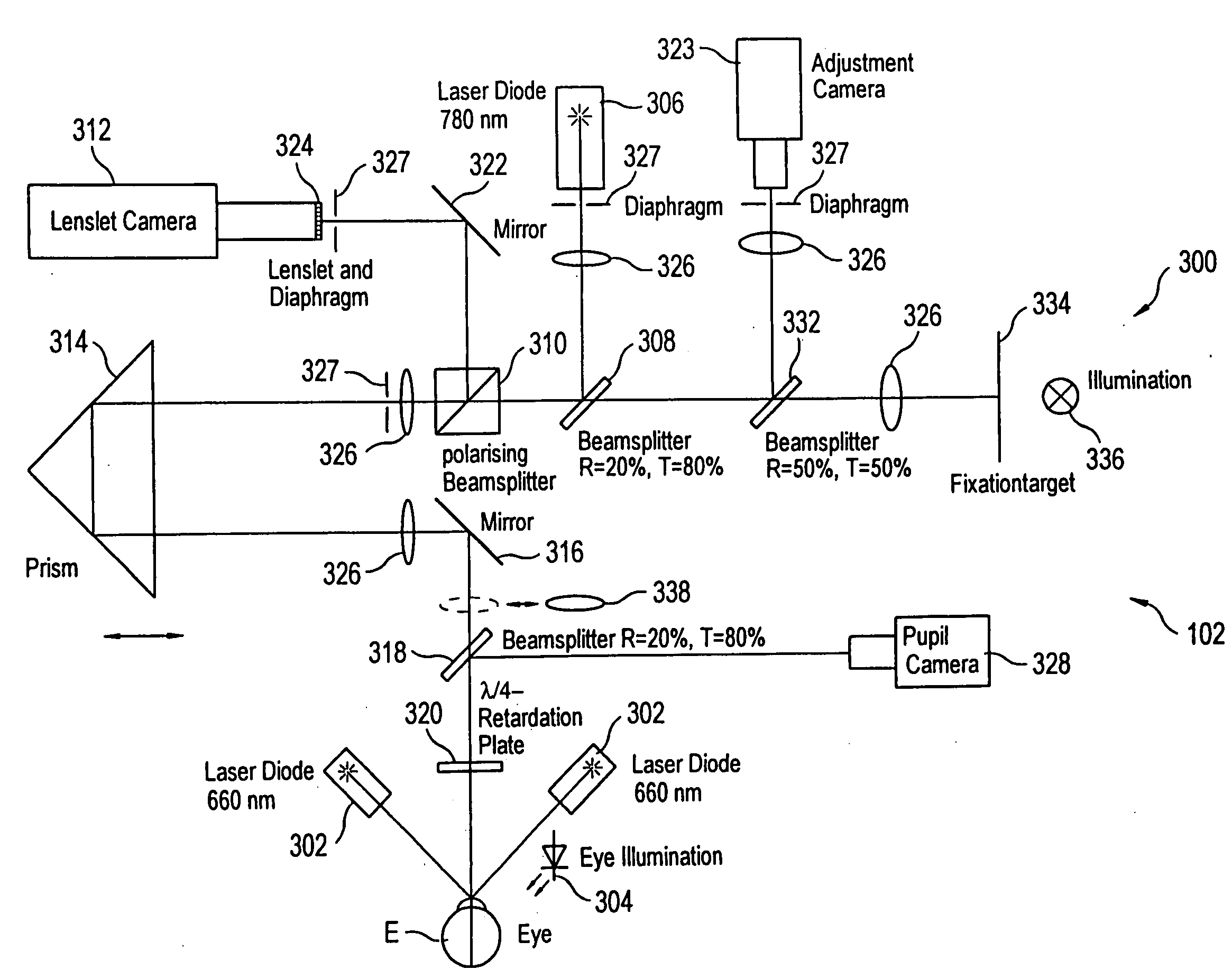
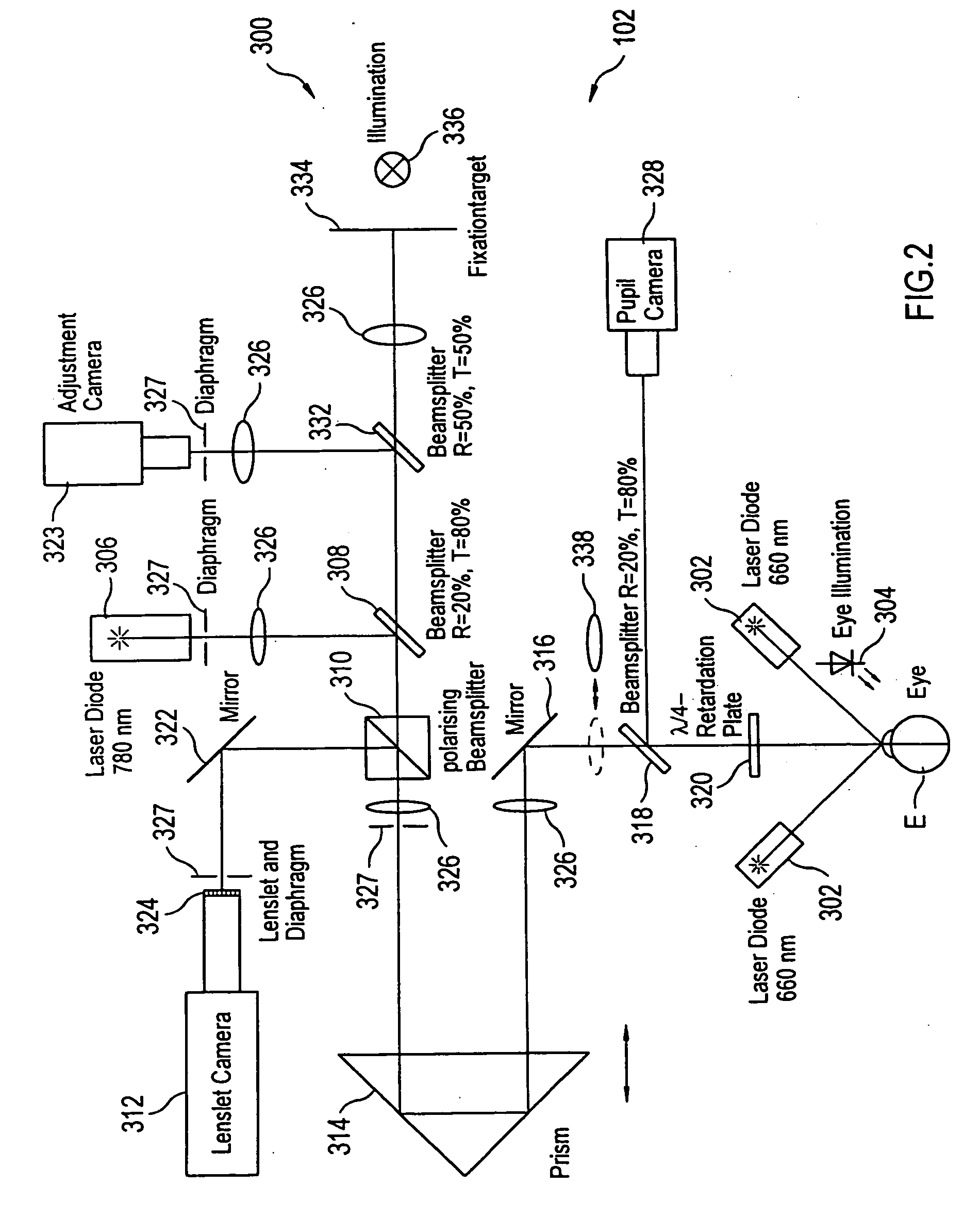
[0029] Turning to FIG. 2, a block diagram of a wavefront sensor 300 (Aberrometer™) is illustrated, which is a preferred implementation of this invention. The wavefront sensor 300 is similar in concept to the wavefront sensor of Williams, but includes certain features that make it especially useful for receiving iris data and for sharpening the focus of light spots on a sensor used in determining the wavefront aberrations of the eye. Further, a number of the features find general applicability to wavefront measurement devices, including those other than Williams. Such devices include scanning devices that do not have a lenslet array and multiple beam devices, e.g. Tscherning aberrometers and ray tracing aberrometers. In general, the wavefront sensor 300 focuses or scans a light (typically a laser) on the retina of an eye and then analyzes the light returned (i.e., backscattered from the retina) through the lens and corneal optics of the eye and imaged to and focused by a lenslet arra...


PUM


Abstract

An improved wavefront sensor is provided that enhances the initial focus and precision of imaged spots used to determine the monochromatic wave aberrations of the eye. The wavefront sensor includes an adjustment camera that is independent of a lenslet camera. A laser in a lower power mode is projected onto the retina of the eye and is brought into more precise or sharp focus by a control system employing data from the adjustment camera, which aids in focusing the imaged spots. “Trombone”-type optics are used to adjust the focus of the light projected onto the retina and the imaged spots onto a sensor. The laser has a higher power mode used when acquiring data of the imaged spots from the sensor.

Description

CROSS REFERENCE [0001] This application is a divisional of Ser. No. 10 / 110,929, filed Mar. 13, 2003.TECHNICAL FIELD [0002] The invention relates to an ophthalmic wavefront aberration diagnostic tool that includes optical components that enhance its sensitivity. The invention also relates to systems using the improved tool for ophthalmic refractive surgery. BACKGROUND ART [0003] The field of ophthalmology for the past number of years has seen great strides in the development of refractive treatments intended to correct the vision of the eye. These techniques have evolved from the earlier radial keratotomy technique, in which slits in the cornea allowed the cornea to relax and reshape, to present techniques including photorefractive keratectomy (“PRK”), anterior lamellar keratectoiny (“ALK”), laser in situ keratomileusis (“LASIK”), and thermal techniques such as laser thermal keratoplasty (“LTK”). All of these techniques strive to provide a relatively quick but lasting correction of v...

Claims


Application Information

Patent Timeline
Patent Type & Authority Applications(United States)
IPC IPC(8): A61B3/10A61B3/00A61B3/103A61B3/12A61F9/007A61F9/01G01J9/00
CPCA61B3/1015G01J9/00
Inventor YOUSSEFI, GERHARDPOLLAND, HANS-JOACHIMSAPPEL, CHRISTOPH
Owner BARCLAYS BANK PLC AS SUCCESSOR AGENT
Why Eureka
Try Eureka