Circuit and method for reducing voltage spikes due to magnetizing current imbalances and power converter employing the same

a technology of magnetizing current imbalance and circuit, applied in the field of power conversion, can solve the problems of large components, relative large power converters, difficult quantity, etc., and achieve the effect of reducing voltage spikes

Active Publication Date: 2006-07-13
ACLEAP POWER INC
View PDF10 Cites 14 Cited by
  • Summary
  • Abstract
  • Description
  • Claims
  • Application Information

AI Technical Summary

Benefits of technology

[0009] To address the above-discussed deficiencies of the prior art, the present invention provides, for use in a power converter having parallel power trains, a circuit for reducing voltage spikes due to magnetizing current imbalances in the power trains. In one embodiment, the circuit includes: (1) a conductive bypass path coupling nodes between transformer secondary windings and inductors in each of the power trains and configured to provide an alternative path to redirect magnetizing current imbalances from the inductors and (2) a capacitor located in the conductive bypass path.

Problems solved by technology

Some loads require substantial quantities of electric power and consequently a relatively large power converter.
Unfortunately, larger components have two significant disadvantages.
First, they are expensive and harder to obtain in quantity.
Unfortunately, another problem arises; the multiple power trains must work in unison to provide the needed power.
However, if the components of one power train differ in their operation from the components in another, the power trains are unbalanced and may actually supply power to one another in addition to the load.
Imbalanced magnetizing currents forced through inductors, typically located at the output of a power train, cause voltage spikes of such magnitude to overwhelm the rectifying switches changing their electrical characteristics and even destroying them.
Unfortunately, matched components are expensive; many components must be manufactured to yield a suitably matched pair.
However, snubber circuits represent additional circuitry and thus additional cost.
This approach also typically results in additional power dissipation.

Method used


Image

  • Circuit and method for reducing voltage spikes due to magnetizing current imbalances and power converter employing the same
  • Circuit and method for reducing voltage spikes due to magnetizing current imbalances and power converter employing the same
  • Circuit and method for reducing voltage spikes due to magnetizing current imbalances and power converter employing the same

Examples


Embodiment Construction

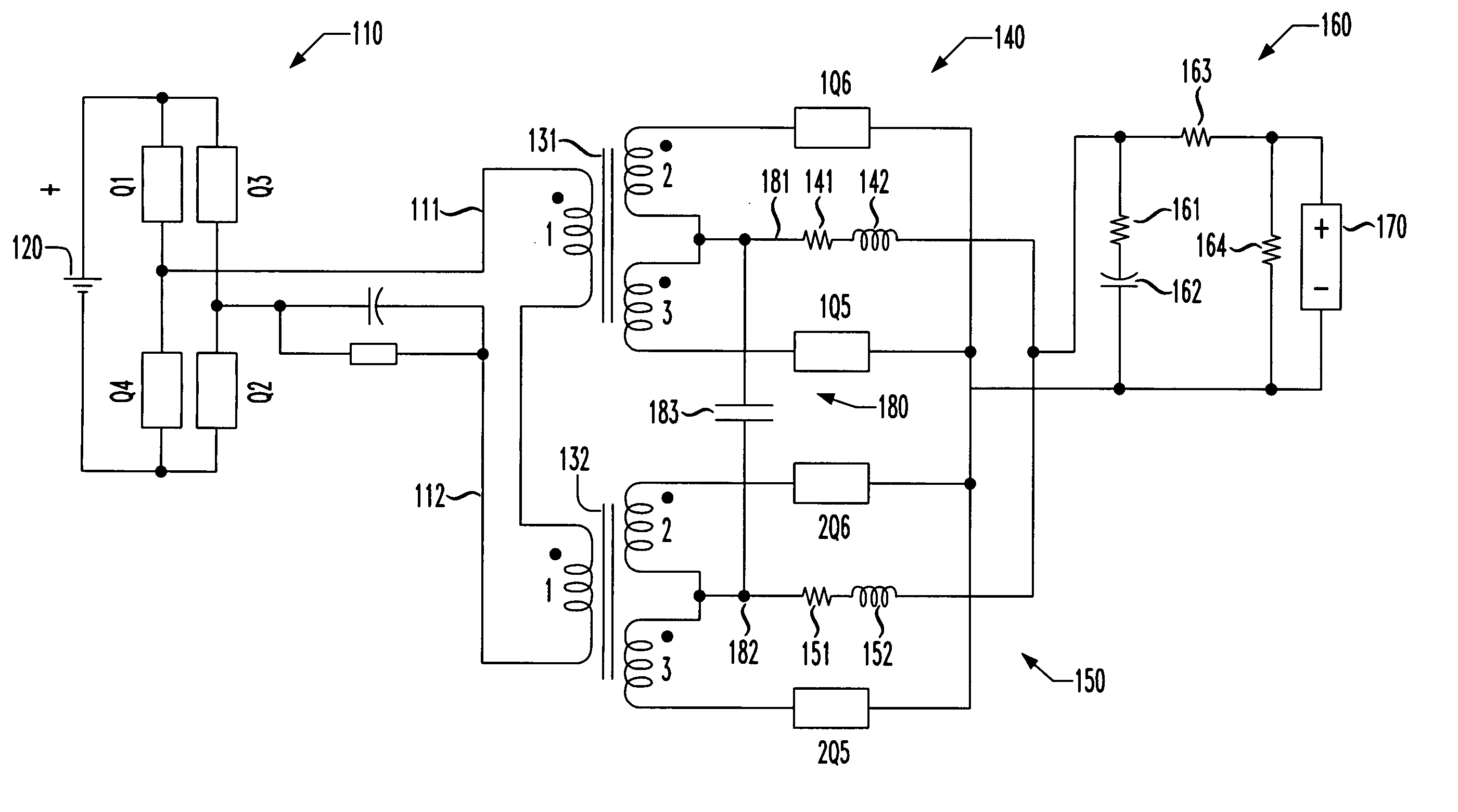
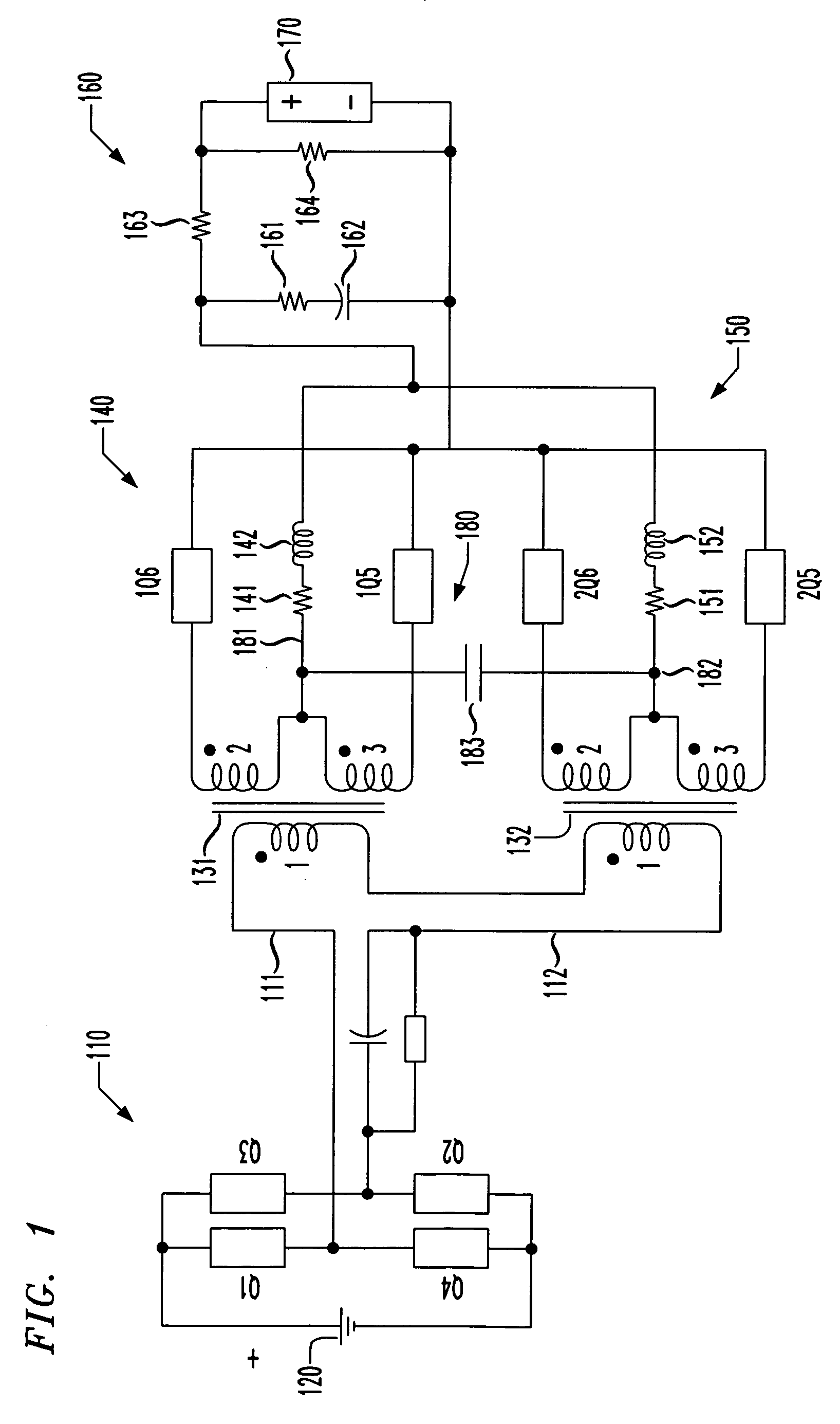
[0017] Referring initially to FIG. 1, illustrated is a schematic diagram of a power converter having first and second power trains. The power converter also includes one embodiment of a circuit for reducing voltage spikes due to magnetizing current imbalances constructed according to the principles of the present invention.

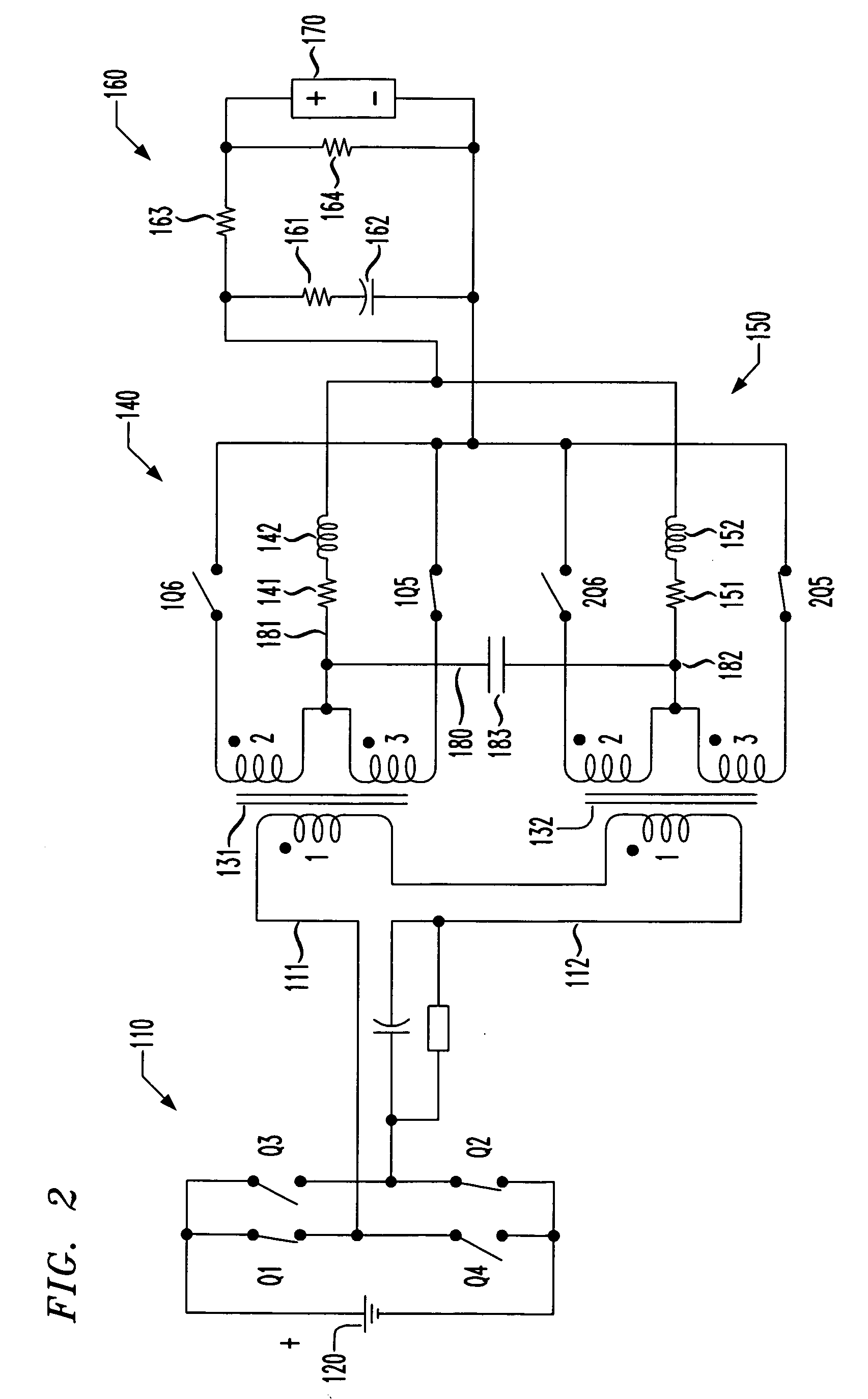
[0018] The power converter has an inverter 110 that is coupled to a source of DC input power 120 and includes first, second, third and fourth switches Q1, Q2, Q3, Q4. As will be shown more completely in conjunction with FIGS. 2A-2D, the switches Q1, Q2, Q3, Q4 cooperate to convert the DC power provided at the source of DC input power 120 into square-wave AC power suitable for charging the electromagnetic field of transformers 131, 132 to alternate polarities. A bus having first and second rails 111, 112 conveys the square-wave AC power to the transformers 131, 132.

[0019] A primary winding “1” is associated with each of the transformers 131, 132 and is coupled to...


PUM


Abstract

For use in a power converter having parallel power trains, a circuit for, and method of, reducing voltage spikes due to magnetizing current imbalances in the power trains and a power converter incorporating the circuit or the method. In one embodiment, the circuit includes: (1) a conductive bypass path coupling nodes between transformer secondary windings and inductors in each of the power trains and configured to provide an alternative path to redirect magnetizing current imbalances from the inductors and (2) a capacitor located in the conductive bypass path.

Description

TECHNICAL FIELD OF THE INVENTION [0001] The present invention is directed, in general, to power conversion and more specifically to a circuit and method for reducing voltage spikes due to magnetizing current imbalances and a power converter that employs such circuit or method. BACKGROUND OF THE INVENTION [0002] Power converters are widely used to provide power having the appropriate electrical characteristics to equipment (“loads”). Power converters convert electric power from one form (e.g., relatively high voltage alternating current, or AC) to another (e.g., lower voltage direct current, or DC). Converters may convert from DC to AC (“inverters”), AC to AC (“cycloconverters”), AC to DC (“rectifiers”) or DC to DC (“switch mode power supplies” or “choppers”). Most power converters operate by using magnetic components, such as transformers and inductors, to transfer or filter electric power. Many power converters use solid state switches (transistors) to make and break electrical con...

Claims


Application Information

Patent Timeline
Patent Type & Authority Applications(United States)
IPC IPC(8): H02M1/12H02J1/02
CPCH02M1/15H02M2003/1555H02M3/1555
Inventor REDDY, RAGHOTHAMAWASSEF, KARIM
Owner ACLEAP POWER INC
Why Eureka
Try Eureka