Eureka AIR delivers breakthrough ideas for toughest innovation challenges, trusted by R&D personnel around the world.

Compensation for temperature and voltage effects when monitoring parameters in a transceiver module

Active Publication Date: 2006-07-13
II VI DELAWARE INC
View PDF37 Cites 18 Cited by
  • Summary
  • Abstract
  • Description
  • Claims
  • Application Information

AI Technical Summary

Benefits of technology

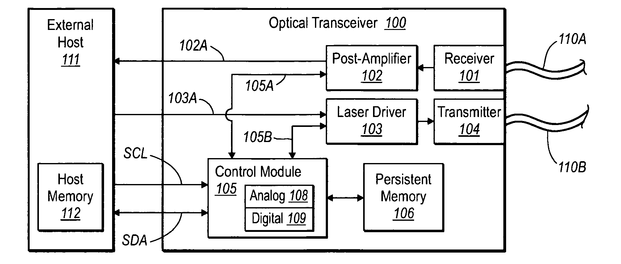
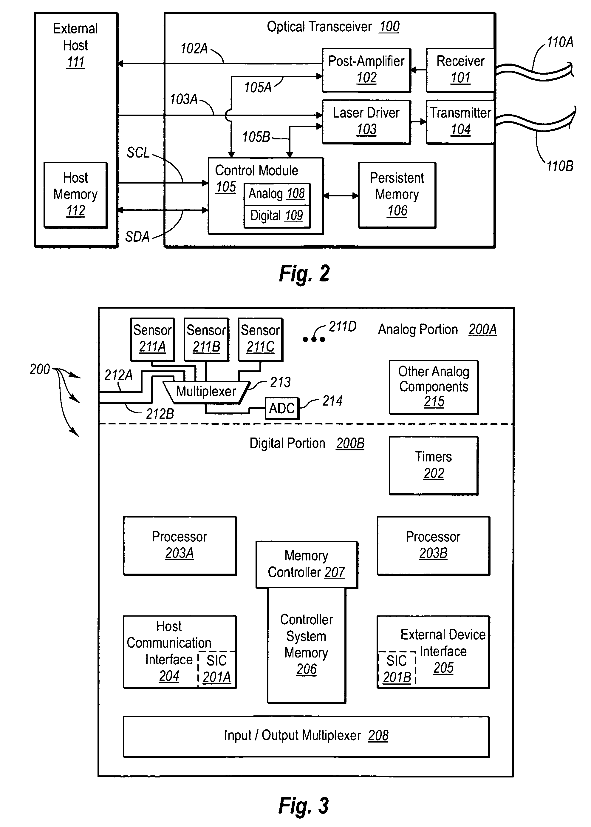
[0011] The foregoing problems with the prior state of the art are overcome by the principles of the present invention, which relate to systems and methods for more accurately estimating the laser power of a laser for an optoelectronic device. The amount of laser power bears on the coupling efficiency into an optic fiber. It would thus be advantageous to be able to accurately determine the laser power which, in turn, assists a user in accurately determining the coupling efficiency of the optical signals. However, conventional methods for measuring laser power have been based on a single calibration of photodiode current and have not been able to capture the complex interrelationship of various environmental and / or operational parameters that can affect laser power or other monitored measurement.
[0012] In one embodiment, an optical transceiver includes a processor, a system memory, and persistent memory. The persistent memory includes microcode that can store a formulaic relationship between laser power and various parameters such as, but not limited to, temperature, voltage, laser bias current, and thermoelectric cooler (“TEC”) current. The interrelationship between the various parameters in the formulaic relationship can be defined in the microcode so as to provide an accurate means by which laser power can be accurately determined. The formulaic relationship represented in the microcode can then be loaded into system memory from the persistent memory, then executed by the processor during operation of the optoelectronic device, together with the sensing by various sensors the data necessary to execute the formulaic relationship. The results of the execution yield an accurate measure of laser power, which measure can then be formatted and provided to a host.
[0013] Accordingly, the principles of the present invention provide for an efficient way to accurately provide a measure of laser power in an optical transceiver module, despite the fact that such a measurement is continually influenced by multiple operational parameters.

Problems solved by technology

However, conventional methods for measuring laser power have been based on a single calibration of photodiode current and have not been able to capture the complex interrelationship of various environmental and / or operational parameters that can affect laser power or other monitored measurement.

Method used


Image

  • Compensation for temperature and voltage effects when monitoring parameters in a transceiver module
  • Compensation for temperature and voltage effects when monitoring parameters in a transceiver module
  • Compensation for temperature and voltage effects when monitoring parameters in a transceiver module

Examples


Embodiment Construction

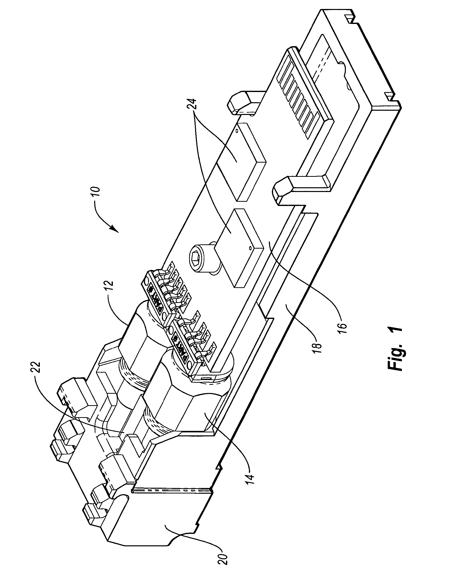
[0021] The present invention is directed to systems and methods for providing accurate calculations of monitored parameters relating to the operation of an optoelectronic device, such as an optical transceiver module (“optical transceiver” or “transceiver”). One monitored parameter of particular interest is laser power, or the amount of light emitted from a laser diode or other light source included in the transceiver. Laser power in one embodiment is calculated by accurately monitoring diagnostic data of the transceiver, then using the diagnostic data to calculate laser power according to a formulaic relationship that is stored and executed within the transceiver. Accurate calculations of laser power can help ensure, for instance, that sufficient coupling efficiency targets are achieved, or that proper eye safety is maintained by preventing operation of the laser when laser power exceeds permitted thresholds.

[0022] As used herein, the term “manufacturer” will refer to an entity th...


PUM


Abstract

A method for calibrating the calculation of a laser power measurement with respect to specified operational and / or environmental parameters in an optoelectronic device, such as an optical transceiver module having a laser diode, is disclosed. In particular, the method includes sensing analog data that relates to light emission from the laser diode using a monitor photodiode disposed in the optical transceiver module. Additional sensors are then used to sense analog data that relates to the temperature and voltage of the monitor photodiode. The analog data is converted into digital data, then a formulaic relationship that relates the light emission data to the temperature and voltage data is used to calculate the laser power of the laser diode. Calibration by this method accounts for unintended effects caused by temperature and voltage fluctuations in the optical transceiver module.

Description

CROSS-REFERENCE TO RELATED APPLICATIONS [0001] This application claims the benefit of the U.S. Provisional Patent Application No. 60 / 643,285, filed Jan. 12, 2005, and entitled “Compensation for Temperature and Current Effects in Transceiver Module,” which is incorporated herein by reference in its entirety.BACKGROUND OF THE INVENTION [0002] 1. The Field of the Invention [0003] The present invention relates generally to optoelectronic devices. More specifically, the present invention relates to optoelectronic devices that use microcode to account for temperature and current effects as well as other diagnostic parameters to determine the laser power for optoelectronic devices. [0004] 2. The Related Technology [0005] Computing and networking technology have transformed our world. As the amount of information communicated over networks has increased, high speed transmission has become ever more critical. Many high speed data transmission networks rely on optical transceivers and similar...

Claims


Application Information

Patent Timeline
IPC IPC(8): H04B10/00
CPCH04B10/504H04B10/58H04B10/40
Inventor NELSON, STEPHEN TODDKAMATH, KISHORE
Owner II VI DELAWARE INC
Why Eureka
Eureka Blog
Learn More