Electrically tuned resonance circuit using piezo and magnetostrictive materials

Inactive Publication Date: 2006-07-13
THE BOEING CO
View PDF13 Cites 27 Cited by
  • Summary
  • Abstract
  • Description
  • Claims
  • Application Information

AI Technical Summary

Benefits of technology

[0006] In an alternative preferred embodiment an ultrasonic sensor is provided. The sensor includes a piezoelectric wafer secured to a structure experiencing an unknown vibration signal. The piezoelectric wafer is secured in parallel with a magnetostrictive inductor that forms an LC circuit. A user control is used to control a biasing system that applies at l

Problems solved by technology

However, modern transmitters often change frequency at millisecond time intervals, which precludes mechanic

Method used


Image

  • Electrically tuned resonance circuit using piezo and magnetostrictive materials
  • Electrically tuned resonance circuit using piezo and magnetostrictive materials

Examples


Embodiment Construction

[0012] The following description of the preferred embodiment(s) is merely exemplary in nature and is in no way intended to limit the invention, its application, or uses.

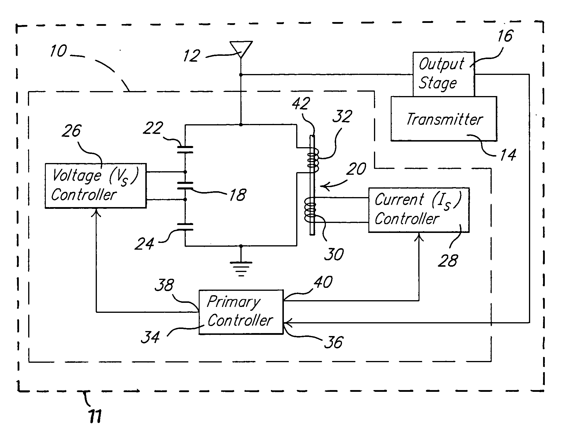
[0013] Referring to FIG. 1, an impedance matching system 10 is shown in accordance with a preferred embodiment of the present invention. The impedance matching system 10 is included within a cellular telephone 11. The system 10 is electrically coupled to an antenna element 12 and to an output stage 16 of an electromagnetic wave transmitter 14. The system 10, however, can be employed in any application where it is desired to match the impedance of a first electrical component with the impedance of a second electrical component.

[0014] The system 10 includes a non-linear piezo capacitor 18 coupled in parallel to a magnetostrictive inductor 20. A pair of blocking capacitors 22 and 24 are coupled in series with the piezo capacitor 18. Voltage blocking capacitors 22 and 24 have a capacitance preferably in the range of ab...


PUM


Abstract

An impedance tuning system, especially for a cellular telephone system. The system can be used to match the impedance of an antenna element with that of an output stage of a transmitter driving the antenna element. The system includes a piezo capacitor in parallel with the magnetostrictive inductor to form an LC circuit. A voltage controller applies a voltage bias signal to the piezo capacitor and a current controller applies a current bias signal to the inductor. A primary controller monitors the frequency of the output signal from the transmitter and controls the voltage and current controllers as needed to alter the impedance of the system as needed to match the impedance of the antenna element with that of the output stage of the transmitter. In an alternative form an ultrasonic sensor is provided.

Description

FIELD OF THE INVENTION [0001] This invention relates to antenna tuning devices, and more particularly to an electrically controlled antenna tuning circuit that matches an impedance of a transmitter with the impedance of an antenna element associated with the transmitter. BACKGROUND OF THE INVENTION [0002] For optical performance, electromagnetic wave transmitters require that the transmitter output stage impedance match the antenna that the transmitter is driving. The impedance match is a function of frequency. Accordingly, a variation in the frequency of the signal being output from the transmitter alters its output impedance, thus requiring the antenna impedance to change, too, to maintain the impedance match. [0003] Traditionally, impedance matching has been accomplished with mechanical tuned inductors and capacitors. However, modern transmitters often change frequency at millisecond time intervals, which precludes mechanical adjustments to inductors and / or capacitors. Thus, with...

Claims


Application Information

Patent Timeline
IPC IPC(8): H04B1/44
CPCH01Q3/44H03J3/16H03J3/22H04B1/0458
Inventor CLINGMAN, DAN J.CALKINS, FREDERICK T.
Owner THE BOEING CO
Why Eureka
Try Eureka