Waste heat recovery system and thermoelectric conversion system

a heat recovery system and heat recovery technology, applied in the direction of machines/engines, laminated elements, lighting and heating apparatus, etc., can solve the problems of insufficient effect, low performance of conventional thermoelectric conversion elements, and inability to effectively convert, etc., to achieve efficient utilization, reduce fuel consumption, and enhance heat transfer

Inactive Publication Date: 2006-07-20
SHOWA DENKO KK
View PDF4 Cites 198 Cited by
  • Summary
  • Abstract
  • Description
  • Claims
  • Application Information

AI Technical Summary

Benefits of technology

[0013] An object of the present invention is to provide a waste heat recovery system capable of generating high power.
[0014] Another object of the present invention is to provide a thermoelectric conversion unit having excellent thermoelectric conversion efficiency and capable of generating high power.

Problems solved by technology

However, since hybrid cars employ numerous pieces of equipment and are of special specifications, diffusion thereof may be limited, and thus contribution thereof to energy conservation is limited.
Conventional thermoelectric conversion elements are too low in performance to effectively convert heat of exhaust gas to electricity and thus have failed to exhibit sufficient effect.

Method used


Image

  • Waste heat recovery system and thermoelectric conversion system
  • Waste heat recovery system and thermoelectric conversion system
  • Waste heat recovery system and thermoelectric conversion system

Examples


Embodiment Construction

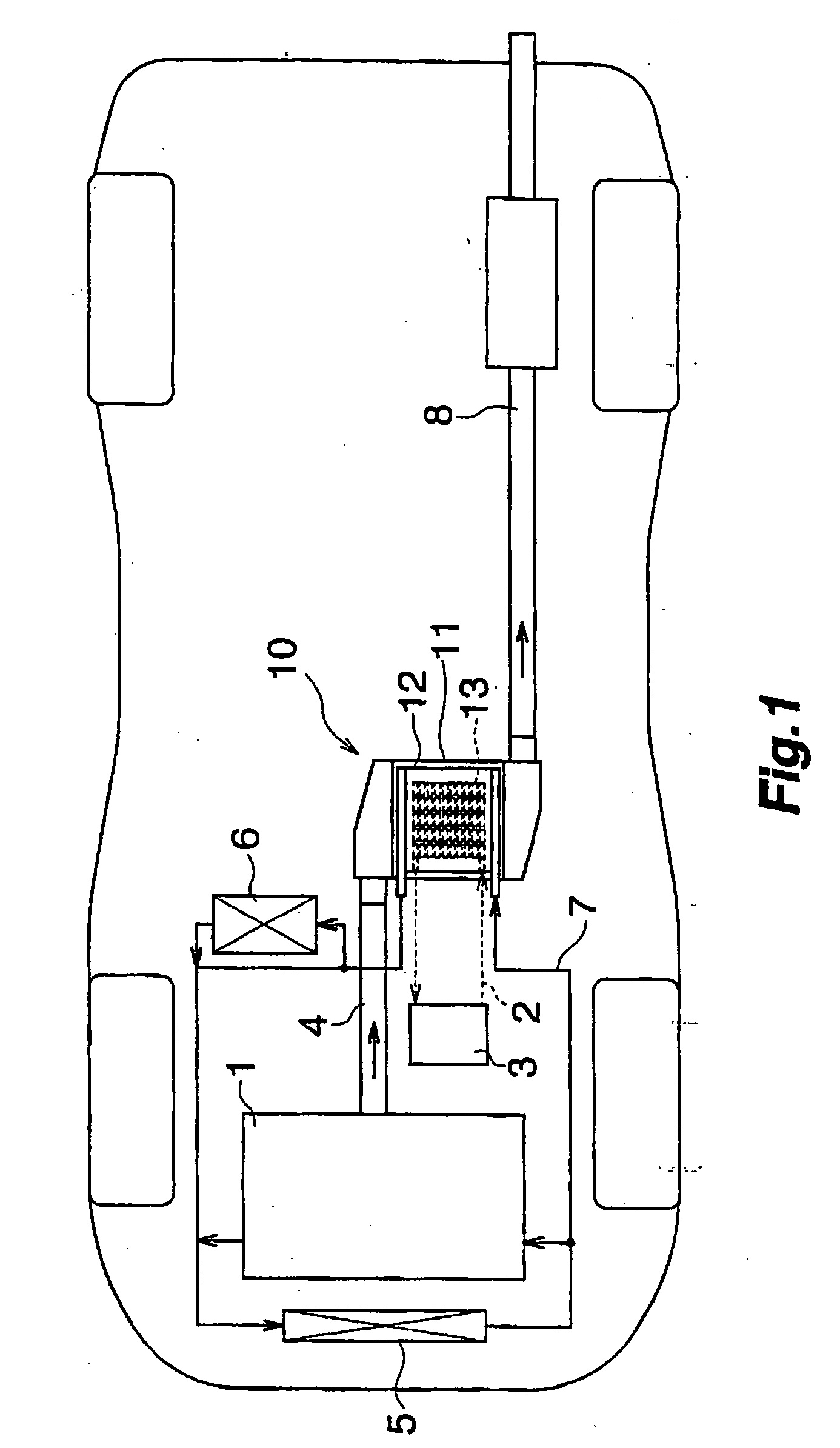
[0048] An embodiment of the present invention will next be described in detail with reference to the drawings. The present embodiment is an application of a waste heat recovery system according to the present invention to recovery of waste heat from exhaust gas emitted from an automobile engine.

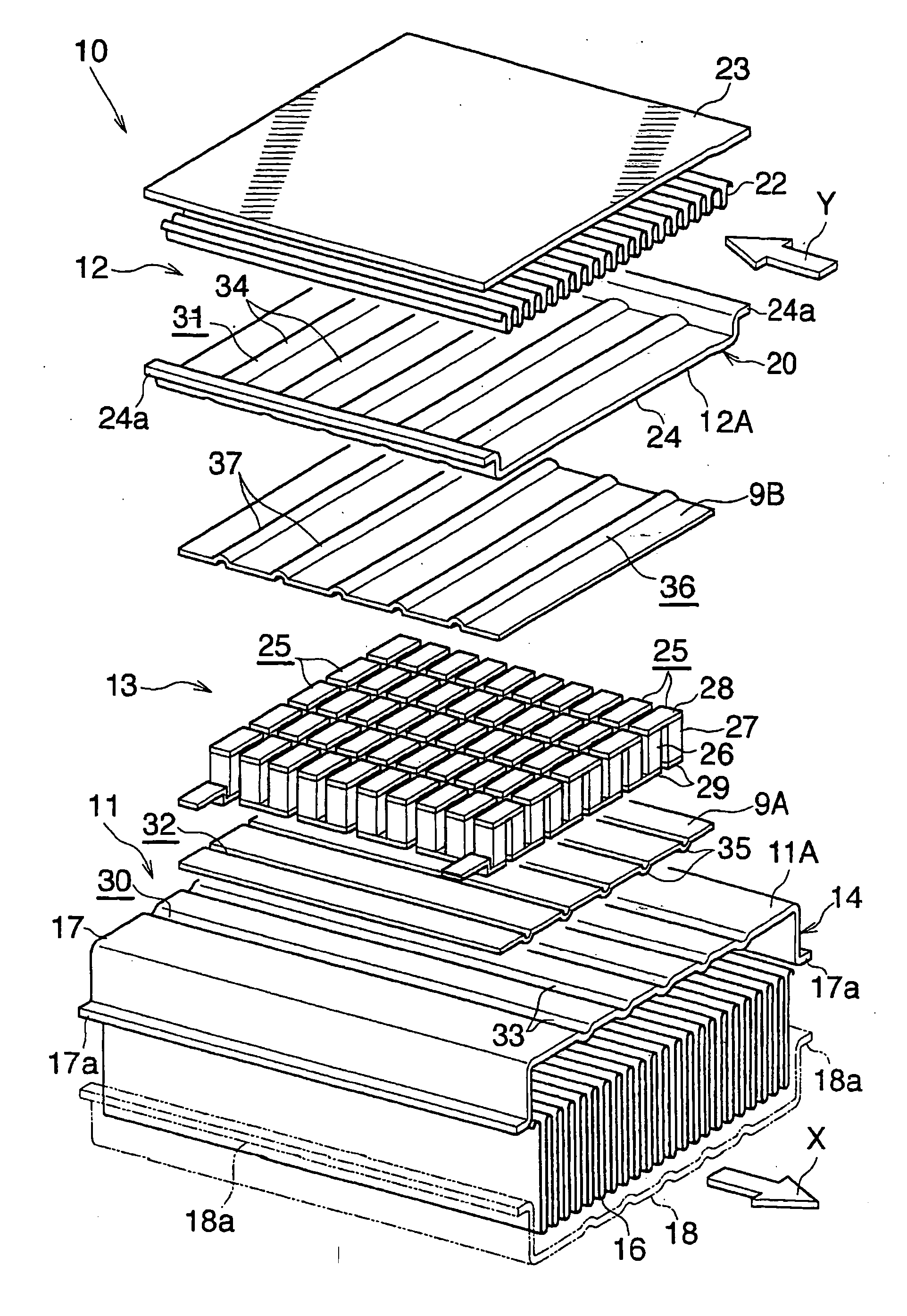
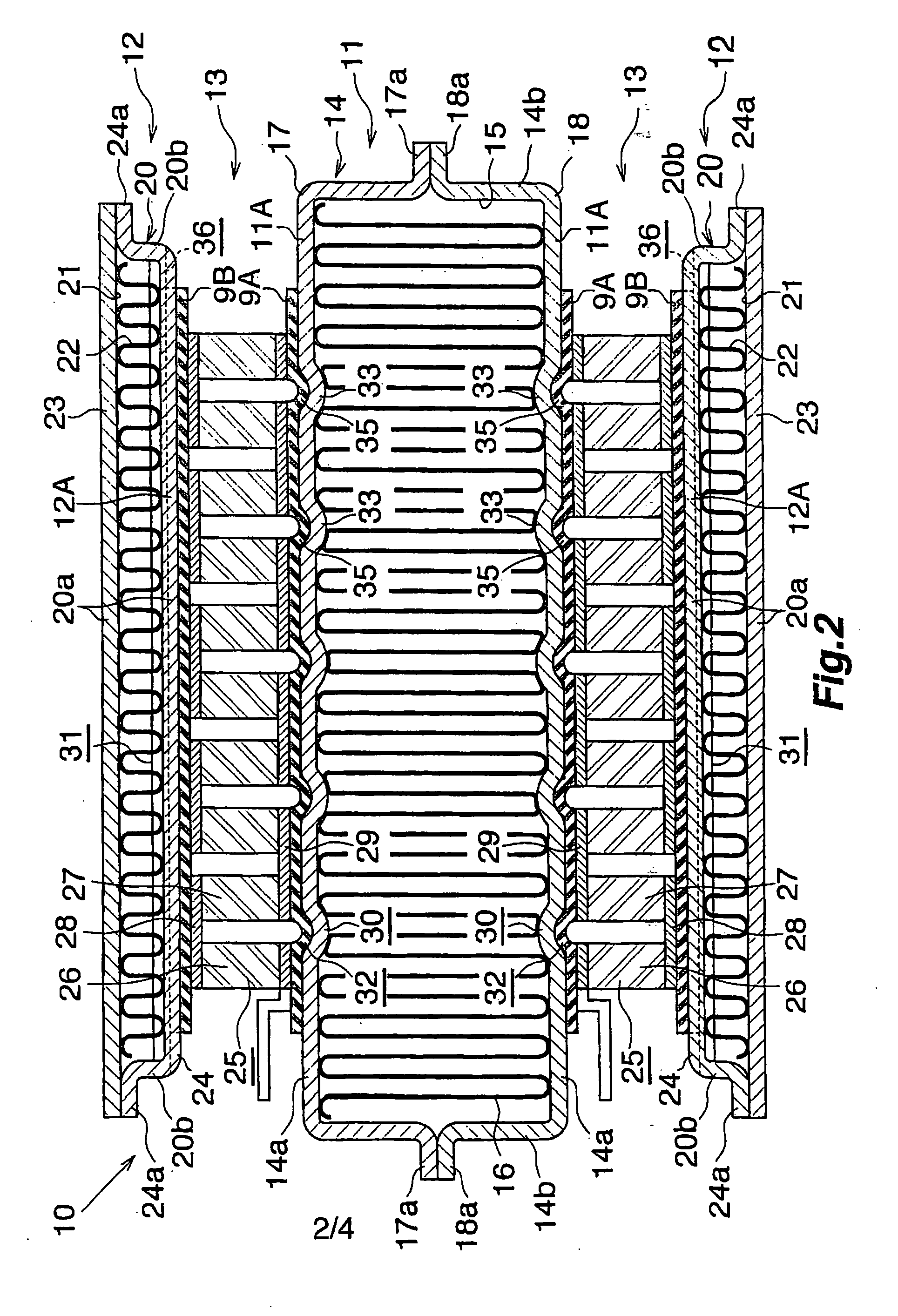
[0049]FIG. 1 schematically shows the configuration of the waste heat recovery system equipped in an automobile. FIGS. 2 and 3 specifically shows the configuration of a thermoelectric conversion unit of the waste heat recovery system.

[0050] Referring to FIG. 1, the waste heat recovery system includes a thermoelectric conversion unit (10) for converting thermal energy of exhaust gas of an engine (1) to electric energy. The thermoelectric conversion unit (10) is connected to a battery (3) via battery charge wiring (2), so that power generated in the thermoelectric conversion unit (10) is charged to the battery (3).

[0051] A high-temperature side of the thermoelectric conversion unit (10) is co...


PUM


Abstract

A waste heat recover system includes a mechanism for supplying power by use of a thermoelectric conversion unit, and a mechanism for utilizing heat released from the thermoelectric conversion unit. Heat released from the thermoelectric conversion unit is utilized for, for example, heating, defrosting, defogging, temperature keeping of fuel, temperature keeping of an internal combustion engine, and temperature keeping of a fuel cell. The waste heat recovery system is equipped in, for example, cars, incinerators, fuel cells, and industrial machinery.

Description

CROSS REFERENCE TO RELATED APPLICATIONS [0001] This application is an application filed under 35 U.S.C. § 111(a) claiming the benefit pursuant to 35 U.S.C. § 119(e)(1) of the filing date of Provisional Application No. 60 / 643,724 filed Jan. 14, 2005 pursuant to 35 U.S.C. § 111(b).BACKGROUND OF THE INVENTION [0002] The present invention relates to a waste heat recovery system in which a thermoelectric conversion unit converts waste heat to electricity and in which warm water is obtained and used for heating, defrosting, or the like. [0003] In the present specification and claims, the term “aluminum” encompasses aluminum alloys in addition to pure aluminum. The upper, lower, left-hand, and right-hand sides of FIG. 2 will be referred to as “upper,”“lower,”“left,” and “right,” respectively. Further, the near side of paper of FIG. 2 (direction indicated by arrow X in FIG. 3) will be referred to as the “front,” and the opposite side as the “rear. [0004] In recent years, awareness of the en...

Claims


Application Information

Patent Timeline
Patent Type & Authority Applications(United States)
IPC IPC(8): H01L35/30H01L35/28
CPCF01N5/025F01P2060/16F02G5/02F02G5/04F02G2260/00F28F3/025H01L35/30Y02T10/16Y02T10/166F28F2265/26Y02T10/12H10N10/13
Inventor NAKAJIMA, KENICHIROWAKABAYASHI, NOBUHIRO
Owner SHOWA DENKO KK
Why Eureka
Try Eureka