Plasma display panel

Inactive Publication Date: 2006-07-20
SAMSUNG SDI CO LTD
View PDF8 Cites 33 Cited by
  • Summary
  • Abstract
  • Description
  • Claims
  • Application Information

AI Technical Summary

Benefits of technology

[0024] The first and second electrodes may be sustain and scan electrodes and the first and second substrates may be rear and front substrates in a PDP. As described above, according to the PDP of the invention, sustain, scan, and address electrodes are provided between the rear and front substrates. The sustain and scan electrodes are alternately arranged on two sides of adjacent discharge cells and are commonly used by adjacent discharge cells. Protruding portions of the address electrodes are also commonly used by adjacent discharge cells. C

Problems solved by technology

In the cathode sheath region, most of the input power is consumed, but the electron heating efficiency is low.
However, both the increase in the positive column region

Method used


Image

  • Plasma display panel
  • Plasma display panel
  • Plasma display panel

Examples


Embodiment Construction

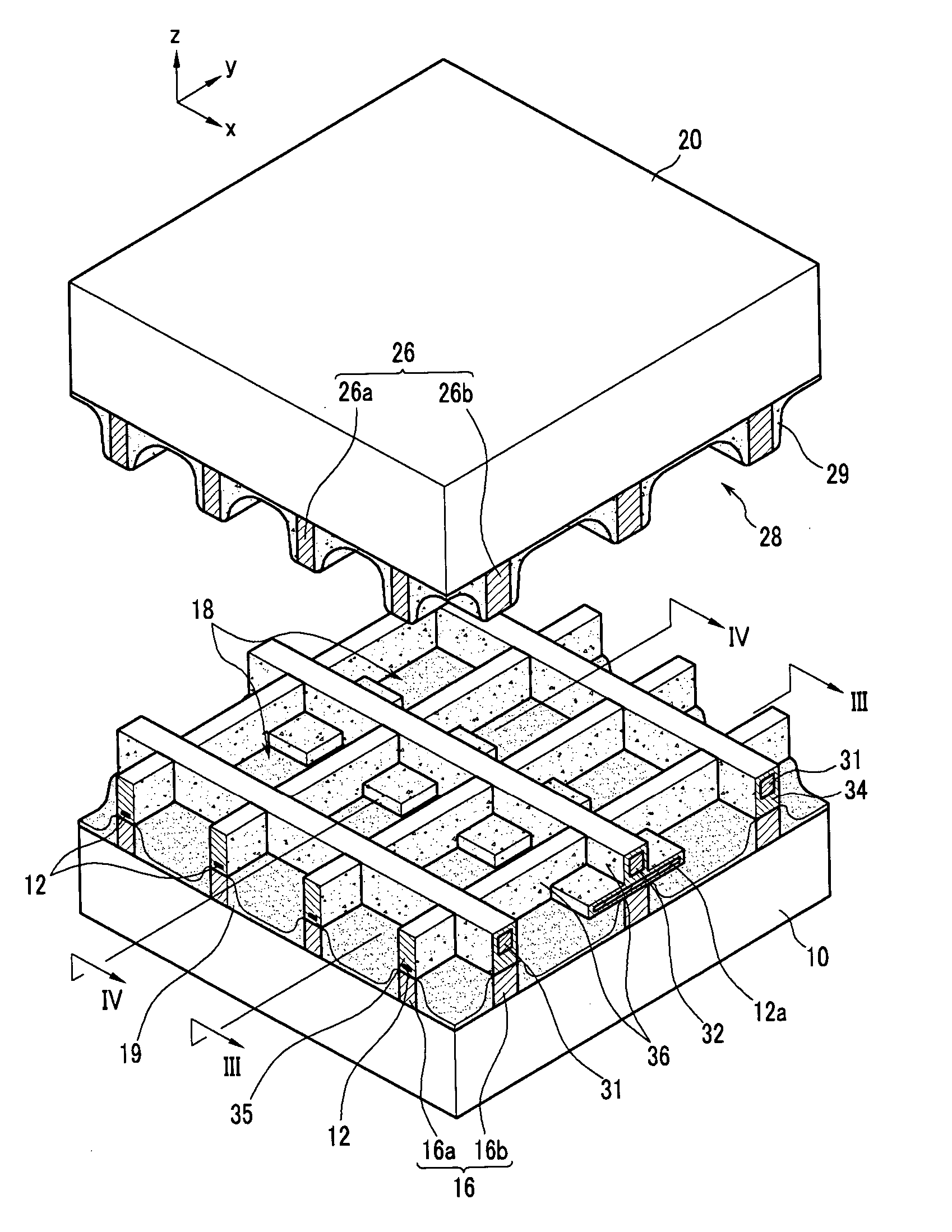
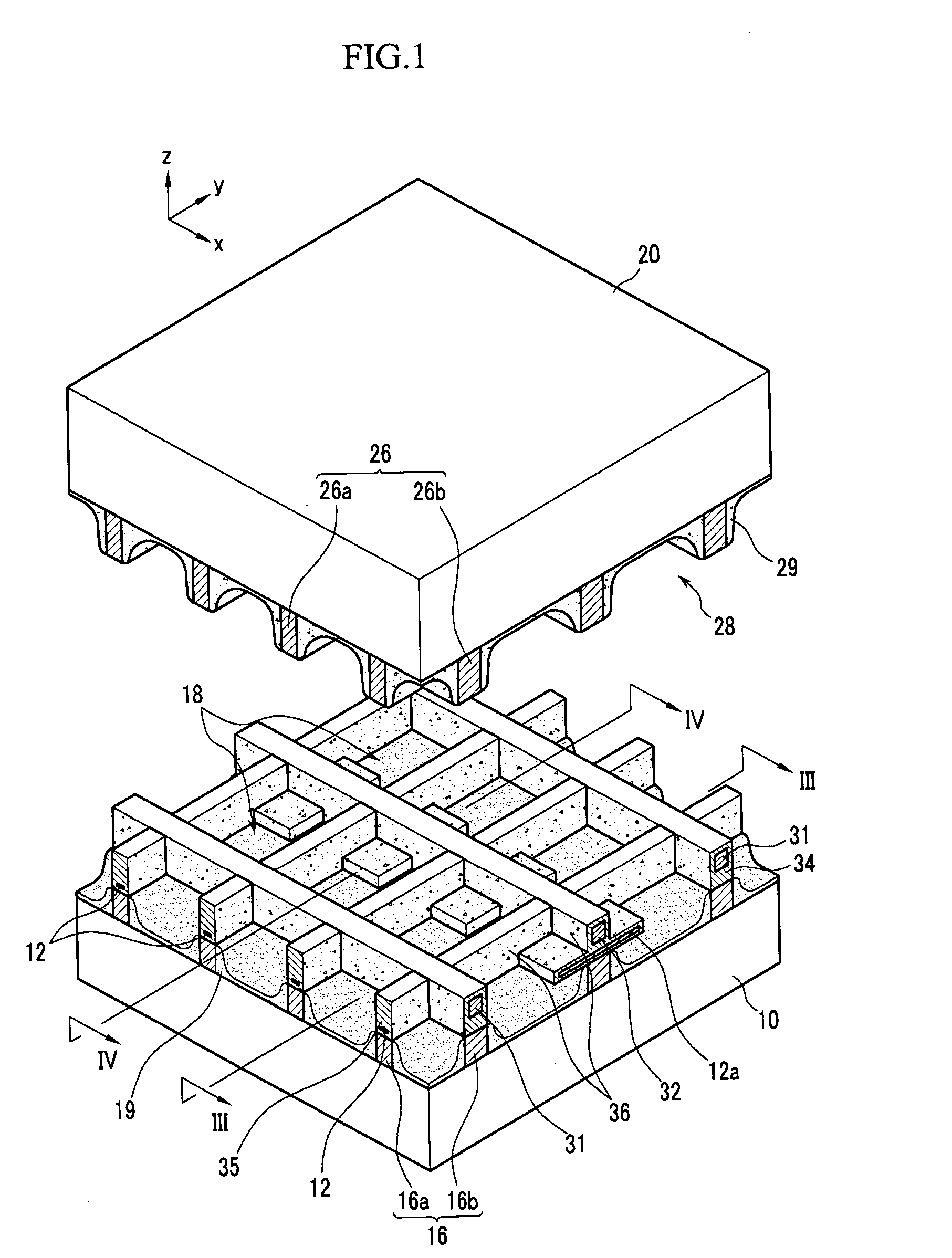
[0031]FIG. 1 is a partially exploded perspective view showing a PDP in accordance with a first embodiment of the invention. The PDP includes a first substrate 10 (hereinafter, referred to as a “rear substrate”) and a second substrate 20 (hereinafter, referred to as a “front substrate”) that are arranged opposite to each other with a predetermined gap in between. The space between the rear and front substrates 10, 20 forms a discharge space. A plurality of discharge cells 17 are formed by partitioning the discharge space between the rear substrate 10 and the front substrate 20. Each discharge cell 17, is formed by a combination of discharge spaces 18 and discharge spaces 28. The discharge space is partitioned by a first barrier rib layer 16 (hereinafter, referred to as a “rear-plate barrier rib”) and a second barrier rib layer 26 (hereinafter, referred to as a “front-plate barrier rib”). Phosphor layers 19, 29 that absorb vacuum ultraviolet rays to emit visible light are formed in th...


PUM


Abstract

A PDP capable of reducing a discharge firing voltage and improving luminescence efficiency using an opposing electrode structure is presented. The PDP includes a first substrate and a second substrate opposite the first, leaving a space in between where a plurality of partitioned discharge cells are formed, phosphor layers formed in the discharge cells, address electrodes formed between the first and second substrates, first and second electrodes formed between the first and second substrates extending orthogonal to the address electrodes and alternately arranged among adjacent discharge cells and each commonly used by the adjacent discharge cells, and dielectric layers formed to cover outer surfaces of the address electrodes and the first and second electrodes. Each of the address electrodes has a protruding portion that protrudes into the discharge cells and is commonly used by adjacent discharge cells sharing the first or second electrodes.

Description

CROSS REFERENCE TO RELATED APPLICATION [0001] This application claims priority to and the benefit of Korean Patent Application No. 10-2005-0005295, filed on Jan. 20, 2005 in the Korean Intellectual Property Office, the entire content of which is incorporated herein by reference FIELD OF THE INVENTION [0002] The present invention relates to a plasma display panel, and more particularly, to a plasma display panel capable of reducing a discharge firing voltage and of improving luminescence efficiency. BACKGROUND OF THE INVENTION [0003] Plasma display panels (PDP) include surface discharge PDP devices and opposing electrode discharge PDP devices. In surface discharge structures, a pair of electrodes which are involved in a sustain discharge are formed on a same plane in a direction perpendicular to a front and rear substrate. Therefore, the sustain discharge occurs between two portions on the same plane, which correspond to the pair of electrodes and are positioned away from each other....

Claims


Application Information

Patent Timeline
IPC IPC(8): H01J17/49H01J11/12H01J11/16H01J11/22H01J11/24H01J11/26H01J11/32H01J11/34H01J11/36H01J11/38H01J11/42
CPCH01J11/16H01J11/26H01J2211/265H01J11/22
Inventor HUR, MINKIM, JAE-ROK
Owner SAMSUNG SDI CO LTD
Why Eureka
Try Eureka