Illumination apparatus and image display apparatus

a technology of image display and illumination apparatus, which is applied in the direction of electric variable regulation, process and machine control, instruments, etc., can solve the problems of complex driving circuit system of such a matrix system as described above, high cost, and low availability of parts such as matrix driving which are ready for such high power driving as described above, so as to reduce size and weight and reduce power consumption

Inactive Publication Date: 2006-07-20
SONY CORP
View PDF10 Cites 107 Cited by
  • Summary
  • Abstract
  • Description
  • Claims
  • Application Information

AI Technical Summary

Benefits of technology

[0035] In short, according to the present invention, it is possible to input an AC voltage to drive a comparatively great number of light emitting diode elements to emit light. This eliminates the necessity for providing, in order to drive the light emitting diode elements, a DC-DC converter for each series connection circuit of light emitting diode elements in such a manner as in the conventional illumination app...

Problems solved by technology

However, the driving circuit system of such a matrix system as described above is complicated and requires a high cost.
Particularly with illumination applications to a backlight or the like, the power consumption by the light emitting diodes is comparatively high.
Under present conditions, parts such as an LSI for implementing matrix driving which are ready for such high power driving as described above are little available.
From such a situation as just described, it is considered impractical to adopt the driving circuit system of the matrix system as a configuration for driving the light source.
As described above, it is considered impractical to perform light emission driving of a large number of light emitting diodes, which em...

Method used


Image

  • Illumination apparatus and image display apparatus
  • Illumination apparatus and image display apparatus
  • Illumination apparatus and image display apparatus

Examples


Embodiment Construction

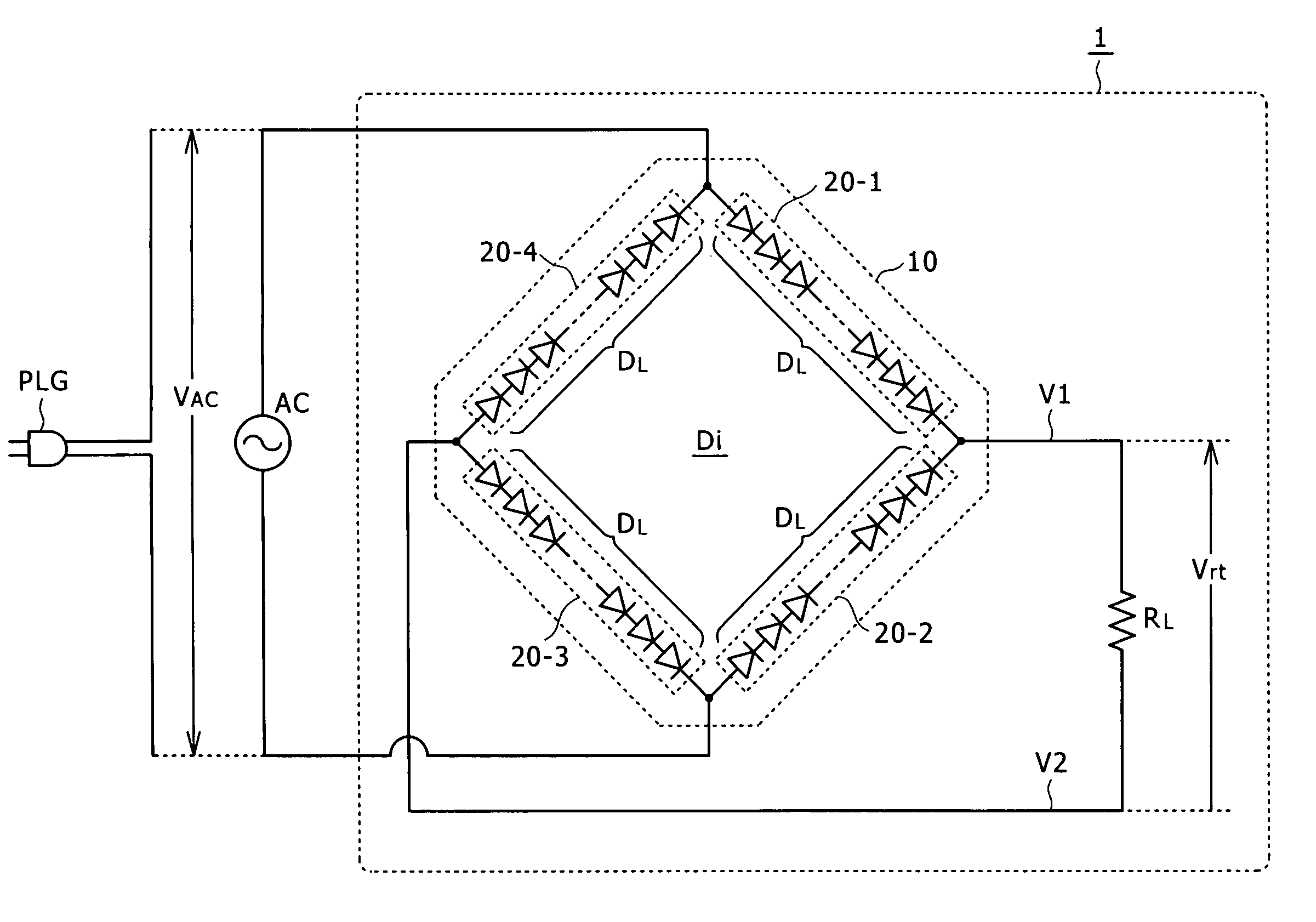
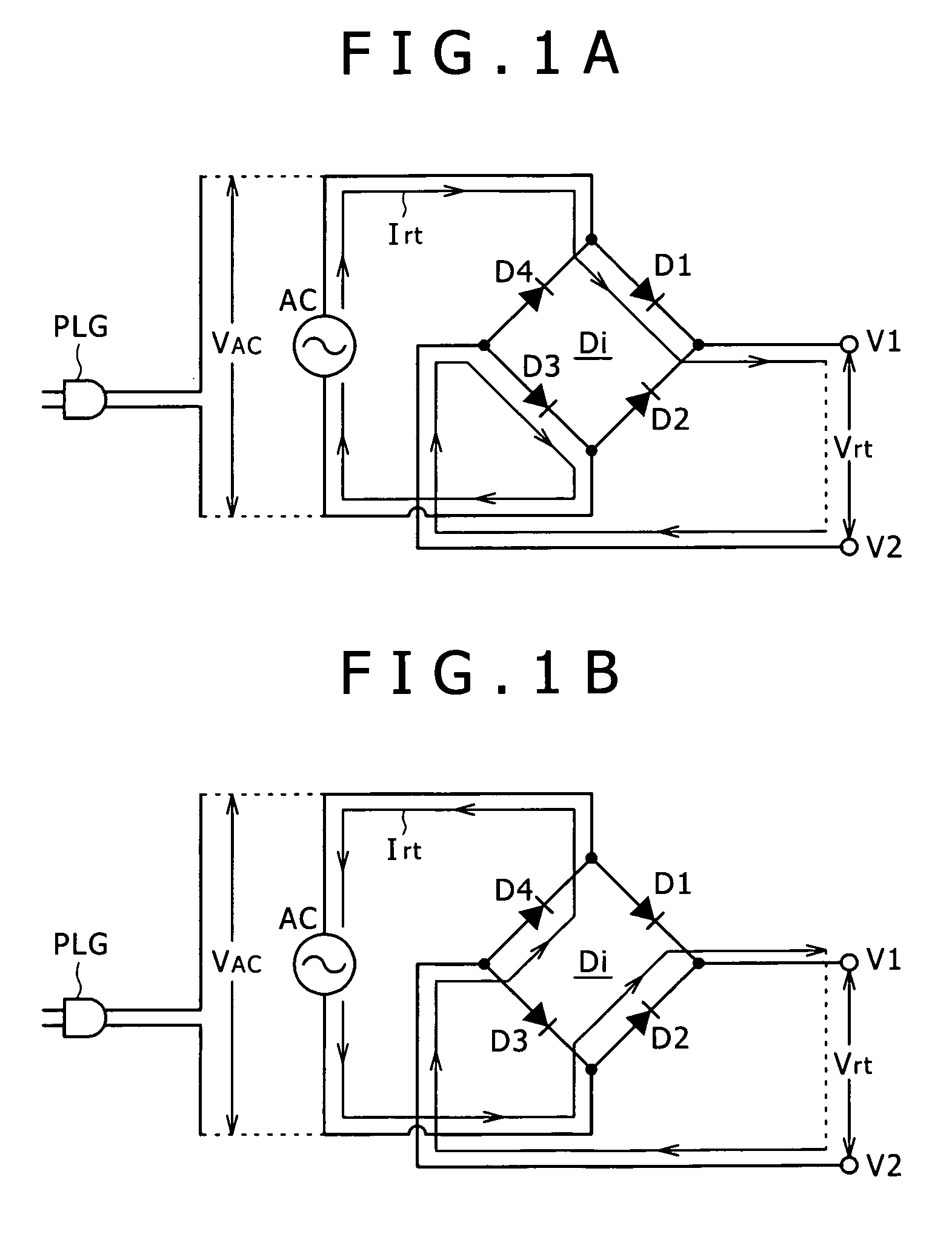
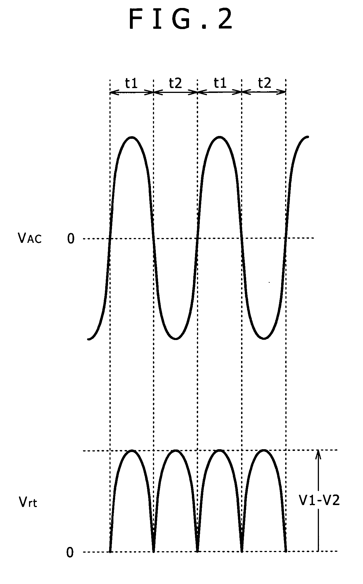
[0060] First, a bridge rectification circuit which is used in an illumination apparatus according to the present invention is described with reference to FIGS. 1A to 3.

[0061] Referring first to FIGS. 1A and 1B, there is shown a bridge rectification circuit Di. The bridge rectification circuit Di includes four rectification diodes D1, D2, D3 and D4 as rectification devices connected in a bridge connection as seen in FIGS. 1A and 1B.

[0062] In the bridge rectification circuit Di, a node between the anode of the rectification diode D1 and the cathode of the rectification diode D4 is used as a positive input terminal and connected to a positive line of an AC voltage AC. Meanwhile, another node between the anode of the rectification diode D2 and the cathode of the rectification diode D3 is used as a negative input terminal and connected to a negative line of the AC voltage AC. The AC voltage AC is supplied actually, for example, by inserting an AC plug PLG into a socket as seen in FIGS....


PUM


Abstract

An illumination apparatus is configured simply in a reduced scale while a light emitting diode is used as a light emitting source for illumination. The illumination apparatus includes an LED driving block including an LED bridge circuit formed from a bridge connection of a plurality of diode series circuits each of which is formed from a series connection of a plurality of light emitting diodes and a rectifying diode. A load resistor is connected to a rectification output of the LED bridge circuit. When an AC voltage is input to the LED driving block, the LED bridge circuit rectifies the AC voltage, and the resulting rectification current is used as driving current to drive the light emitting diodes to emit light.

Description

CROSS-REFERENCE TO RELATED APPLICATIONS [0001] The present application claims priority from Japanese Application No. 2004-371234 filed Dec. 22, 2004, the disclosure of which is hereby incorporated by reference herein. BACKGROUND OF THE INVENTION [0002] This invention relates to an illumination apparatus in which a light emitting diode element is used and an image display apparatus which uses an illumination apparatus of the type described as a light source. [0003] In a display device such as, for example, an LCD (Liquid Crystal Display) device, a light source (illumination apparatus) called backlight is used to display an image by visible radiations. In recent years, an illumination apparatus has been proposed wherein a light emitting diode (LED) element (hereinafter referred to as “light emitting diode”) is used for the backlight. Where a light emitting diode is used for a backlight, usually a technique wherein light emitting diodes which emit lights of the primary colors of red (R...

Claims


Application Information

Patent Timeline
IPC IPC(8): H05B37/00H01L33/00G02F1/133H02M7/538H05B37/02H05B44/00
CPCH05B33/0815H05B33/0821Y02B20/348H05B45/40Y02B20/30H05B45/31
Inventor FURUKAWA, NORIMASA
Owner SONY CORP
Why Eureka
Try Eureka