Thermal printer

Inactive Publication Date: 2006-07-20
FUNAI ELECTRIC CO LTD
View PDF2 Cites 3 Cited by
  • Summary
  • Abstract
  • Description
  • Claims
  • Application Information

AI Technical Summary

Benefits of technology

[0008] It is an object of the present invention to provide a thermal printer that can impr

Problems solved by technology

In addition, in cases in which the head temperature is higher than the predetermined temperature, the energy i

Method used


Image

  • Thermal printer
  • Thermal printer
  • Thermal printer

Examples


Embodiment Construction

[0031] Selected embodiments of the present invention will now be explained with reference to the drawings. It will be apparent to those skilled in the art from this disclosure that the following descriptions of the embodiments of the present invention are provided for illustration only and not for the purpose of limiting the invention as defined by the appended claims and their equivalents.

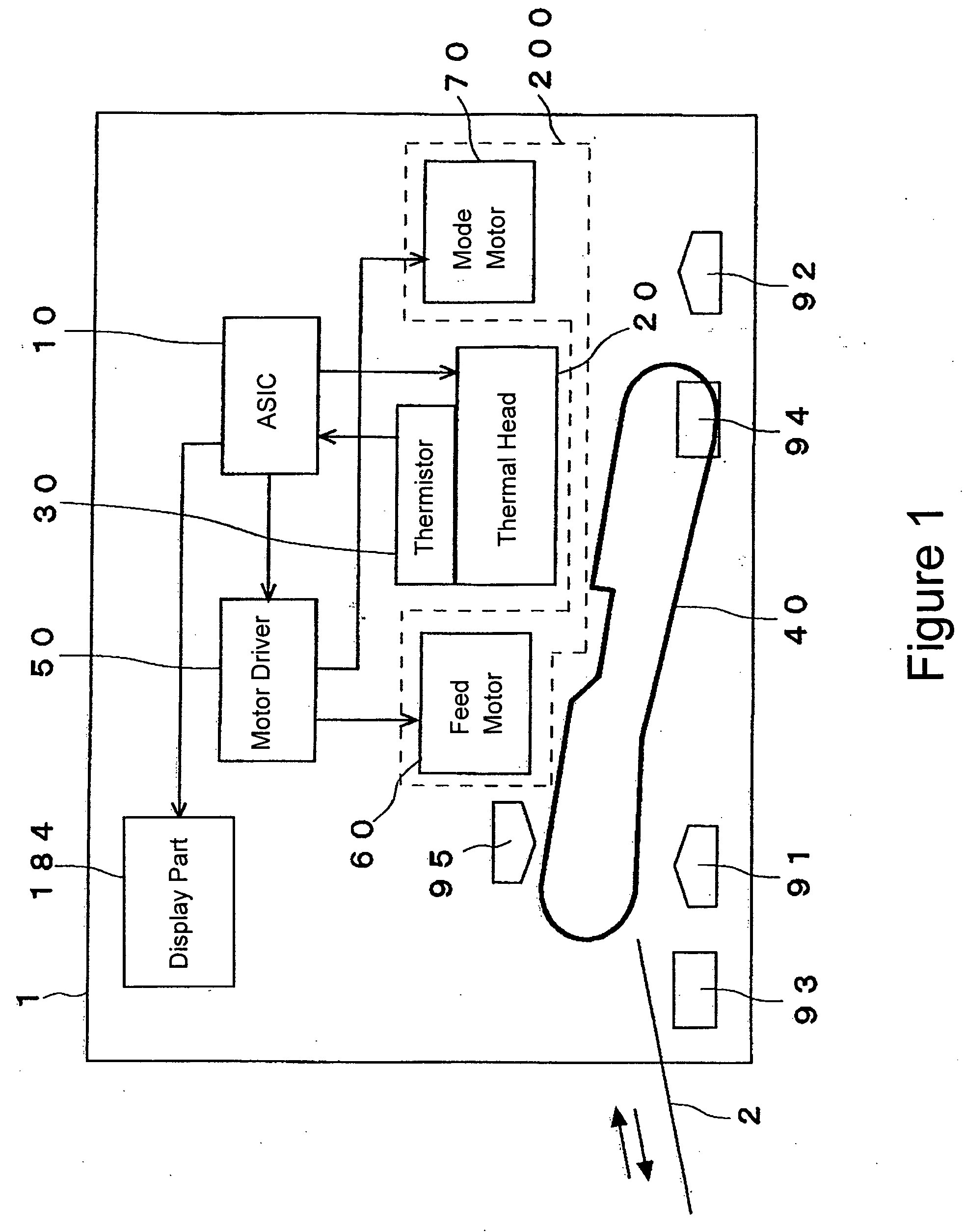
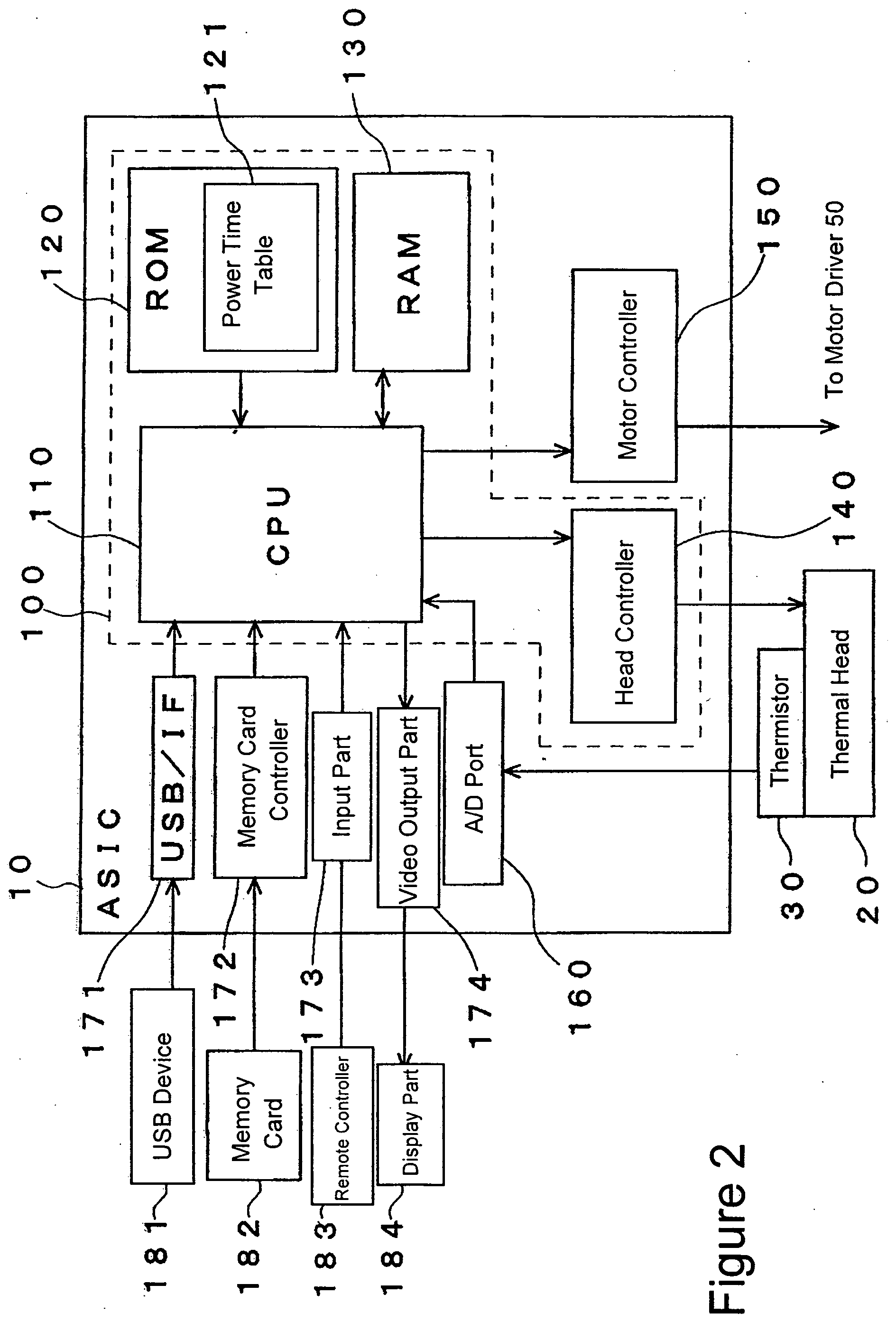
[0032]FIGS. 1 and 2 are block diagrams illustrating a thermal printer 1 in accordance with one embodiment of the present invention. Furthermore, FIG. 2 is a diagram illustrating the ASIC (application specific integrated circuit) 10 in FIG. 1. Moreover, FIG. 3 shows a schematic diagram illustrating the printing system in the thermal printer 1.

[0033] The thermal printer 1 is a so-called sublimation type printer. As is shown in FIG. 1, the thermal printer 1 is constructed so that this printer includes an ASIC 10, a thermal head 20, a thermistor 30, an ink ribbon 40, a motor driver 50, a feed motor ...


PUM


Abstract

A thermal printer performs printing on a paper based on printing density data input. The thermal printer includes a thermal head having at least one heating element; a temperature detector which detects a temperature of the thermal head; and a control part which is connected to the thermal head and the temperature detector, receives the printing density data, and controls an amount of energy to be supplied to the heating element based on the printing density data. The control part stores therein a printing density-energy supply amount table which sets forth an amount of energy to be supplied to the heating element to perform printing with certain printing densities at certain head temperatures. The printing density-energy supply amount table sets forth that the amount of energy to be supplied is greater than zero at the printing density of zero if the head temperature is lower than a predetermined temperature.

Description

BACKGROUND OF THE INVENTION [0001] 1. Field of the Invention [0002] The present invention relates to a thermal printer having a thermal head. [0003] 2. Background Information [0004] In thermal printers, the printing density is generally known to become denser as the temperature of the heating elements of the thermal head increases. Furthermore, the temperature of the heating elements is controlled by controlling the time during which electric power is transmitted to these heating elements. Moreover, each of the heating elements corresponds to a dot of the printed image, and the time during which the electric power is transmitted to these heating elements is controlled for each heating element. These times are set forth beforehand in the form of tables 121P as shown in FIG. 6. In the time table 121P used in a known thermal printer, electric power is not provided to the heating elements that correspond to dots having zero (0) printing density, i.e., dots that are not to perform the pr...

Claims


Application Information

Patent Timeline
IPC IPC(8): B41J2/36
CPCB41J2/36
Inventor NAITO, TADAHIRO
Owner FUNAI ELECTRIC CO LTD
Why Eureka
Try Eureka