Class E amplifier with inductive clamp

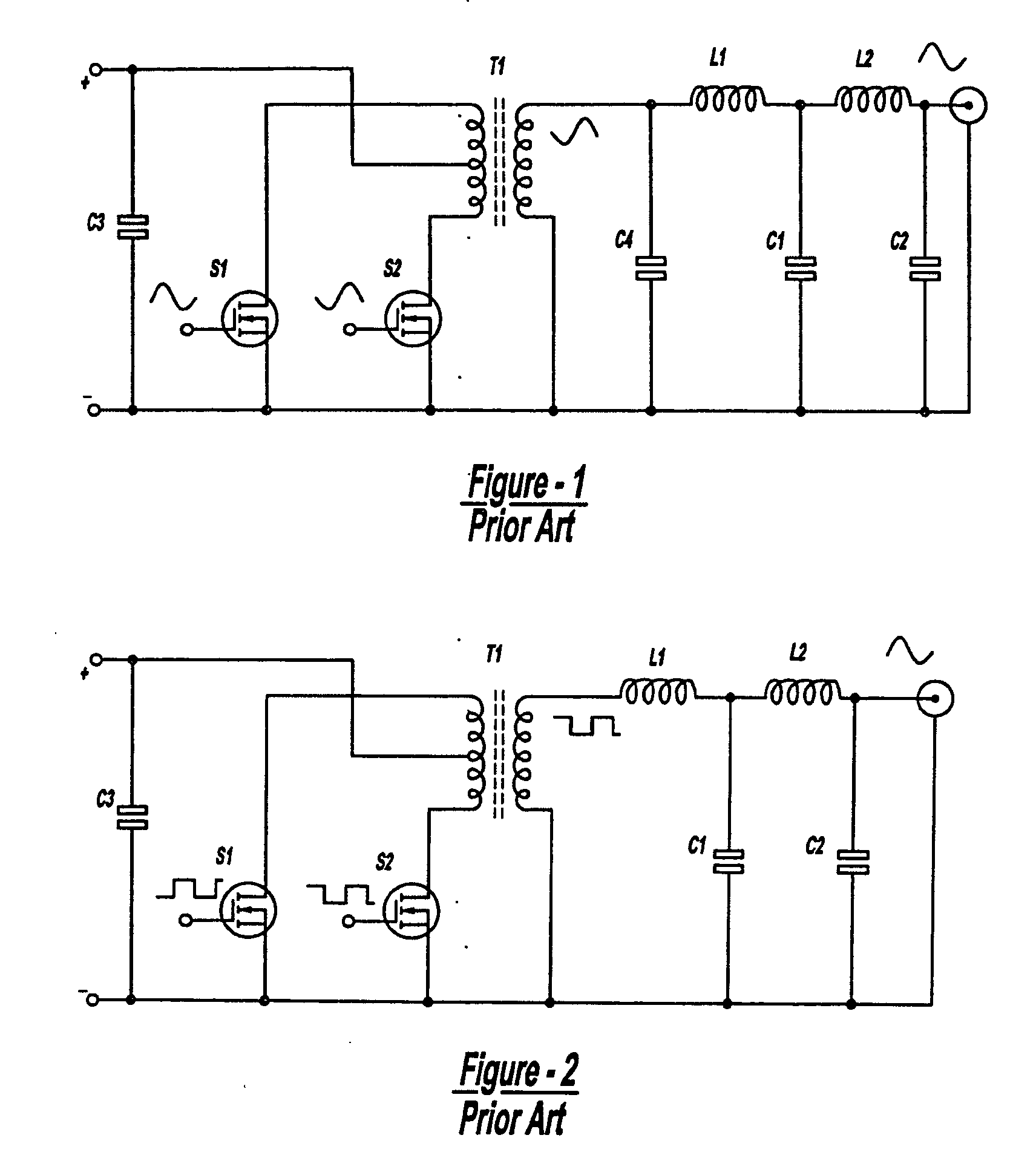
a clamping and amplifier technology, applied in the field of power supplies, can solve the problems of high transistor power dissipation, poor efficiency, and disadvantages of fig. 1

Inactive Publication Date: 2006-07-20
MKS INSTR INC
View PDF66 Cites 47 Cited by
  • Summary
  • Abstract
  • Description
  • Claims
  • Application Information

AI Technical Summary

Benefits of technology

[0018] In yet another aspect of the present invention, a power supply includes a supply output and first and second power supply circuits as defined above. The output of each first and second power circuit is connected in parallel to the supply output. Respective alternating signal sources switch the inverters of the first and second supply circuits and control a circuit for altering the relative phase of the signal sources to adjust the power at the supply output. The power supply circuits may be connected in...

Problems solved by technology

The circuit of FIG. 1 has the disadvantages of poor efficiency and high transistor power dissipation.
To address the high power dissipation, many applications use expensive, special RF transistors which often employ beryllium oxide (BEo) low thermal resistance technology.
This often requires large air or water cooled hea...

Method used


Image

  • Class E amplifier with inductive clamp
  • Class E amplifier with inductive clamp
  • Class E amplifier with inductive clamp

Examples


Embodiment Construction

[0059] The following description of the preferred embodiment(s) is merely exemplary in nature and is in no way intended to limit the invention, its application, or uses.

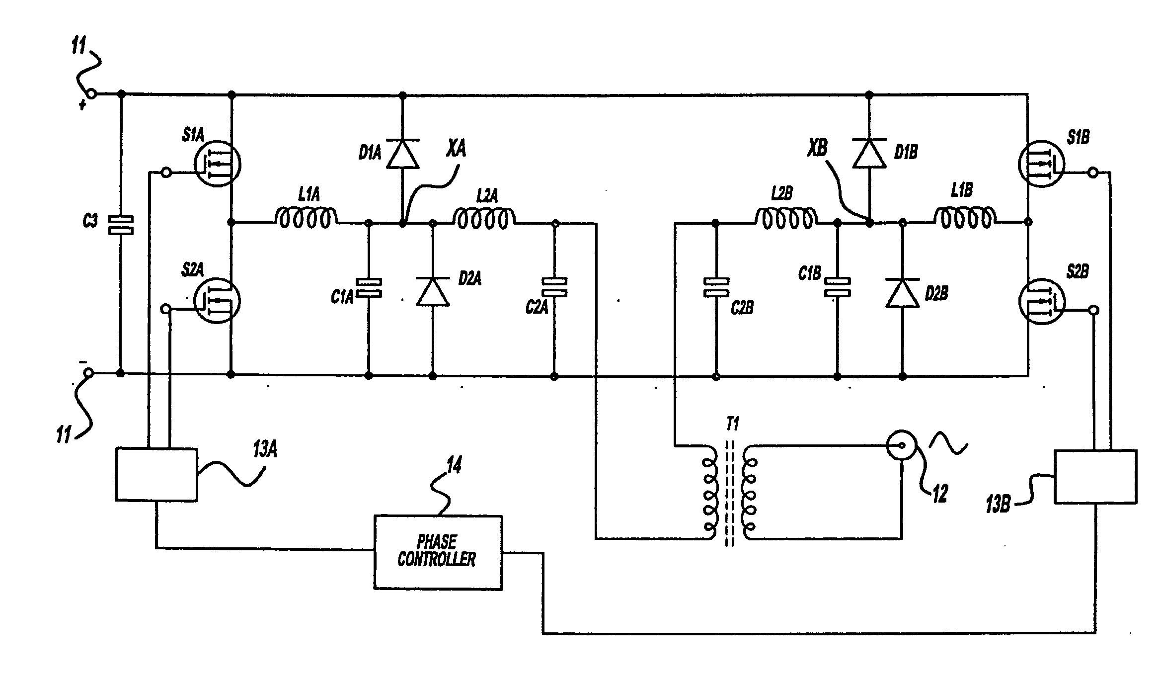
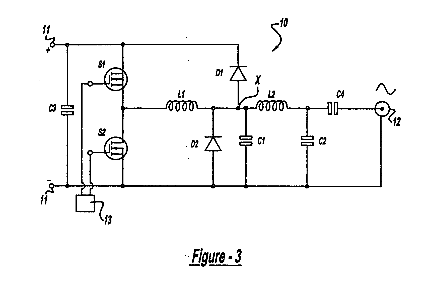
[0060] With reference to FIG. 3, a voltage inverter circuit is generally indicated at 10 and has a direct current (DC) voltage source input at 11 and an alternating current (AC) output at 12. It should be noted from the outset that in describing the figures, switches will generally be referred to using S followed by a number; capacitors will be referred to using C followed by a number; inductors will be referred to using L followed by a number; diodes will be referred to using D followed by a number; and transformers will be referred to using T followed by a number. Further, in circuits which have a generally symmetric topology, each of the above reference symbols may be followed by a letter suffix to indicate generally similar, symmetric elements.

[0061] Switches S1, S2 receive as input respective out of phase squa...


PUM


Abstract

A power supply including an inverter receiving a DC input signal from a DC input source (11). The inverter is implemented as a single-ended inverter. Each inverter is driven by a signal source (13A, 13B), which outputs an AC signal. The output from each inverter is input to a first stage harmonic filter. The power supply includes an output circuit that includes a rectifier (D1) arranged about a point so that if the inverter attempts to drive the point beyond a predetermined voltage, the rectifier conducts in order to return at least one of power and current to the DC input source. The output from the first harmonic filter (L1A, C1; L1B, C1) is output to a second harmonic filter (L2, C2) and is then output from the power supply.

Description

CROSS-REFERENCE TO RELATED APPLICATIONS [0001] This application is a continuation-in-part of U.S. patent application Ser. No. 10 / 657,825, filed Sep. 8, 2003, which is a continuation of U.S. patent application Ser. No. 10 / 227,613, filed Aug. 23, 2002, which is a continuation of U.S. patent application Ser. No. 09 / 763,500 filed Mar. 26, 2001, which is a U.S. National filing of PCT / US00 / 19835 filed Jul. 21, 2000, which claims priority to GB 9917047.4 filed Jul. 22, 1999 and GB0009669.3 filed Apr. 20, 2000. The disclosures of the above applications are incorporated herein by reference.FIELD OF THE INVENTION [0002] This invention relates generally to power supplies for supplying alternating power and, more particularly, to a protection circuit for the switching portion of a power supply where the switching portion of the power supply is implemented as a class E amplifier. BACKGROUND OF THE INVENTION [0003] Radio frequency (RF) energy is used in various industries for the treatment of mat...

Claims


Application Information

Patent Timeline
IPC IPC(8): H02H7/122H03F3/217
CPCH02H7/122H02M7/48H02M7/493H02M7/537H02M7/538H02M7/5387H03F1/52H03F3/2173H03F3/2176H03F2200/33H03F2200/441H02M1/32H03F3/19
Inventor LINCOLN, DANIEL J.BENNETT, PAUL G.
Owner MKS INSTR INC
Why Eureka
Try Eureka