Optical path switch apparatus of optical LAN system

a technology of optical lan system and optical path switch, which is applied in the direction of data switching network, electromagnetic repeater, instruments, etc., can solve the problems of node device being disconnected from the input and output optical fiber cables, affecting the operation of optical path switch, etc., to achieve simple configuration and suppress network crash

Inactive Publication Date: 2006-07-20
PACIFIC INDUSTRIAL CO LTD
View PDF7 Cites 94 Cited by
  • Summary
  • Abstract
  • Description
  • Claims
  • Application Information

AI Technical Summary

Benefits of technology

[0007] Accordingly, it is an objective of the present invention to provide an optical path switch apparatus of...

Problems solved by technology

Thus, if any one of the node devices fails, the optical signal cannot be passed to a node device subsequent to the failed node device, which results in a network crash.
Fu...

Method used


Image

  • Optical path switch apparatus of optical LAN system
  • Optical path switch apparatus of optical LAN system
  • Optical path switch apparatus of optical LAN system

Examples


first embodiment

[0023] the present invention will now be described with reference to the attached drawings.

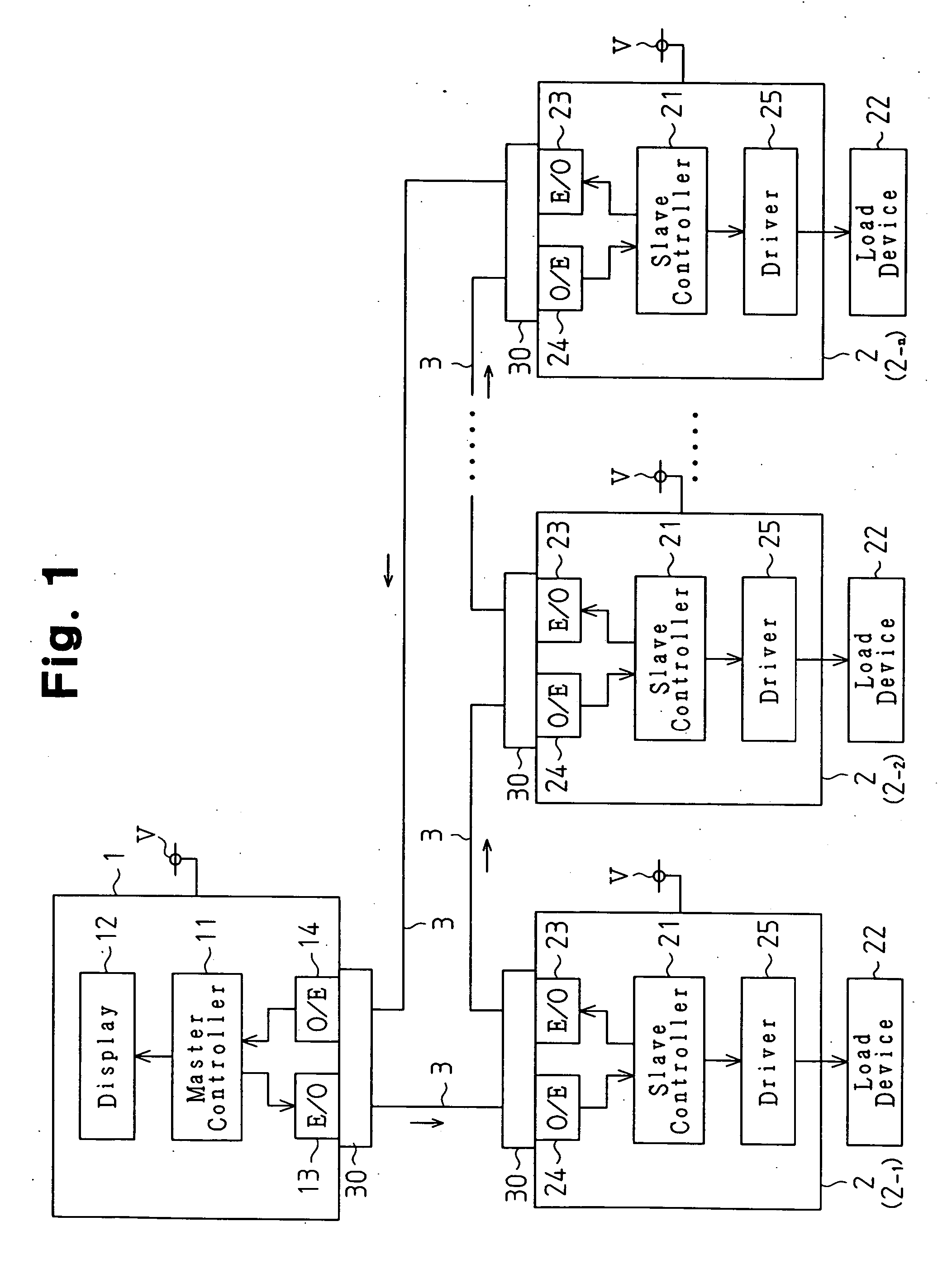
[0024]FIG. 1 shows an optical LAN system according to the first embodiment, or a ring type optical LAN system, which is suitable for the use in vehicles. The system includes a plurality of node devices 1, 2. The node devices 1, 2 include a master node 1 and a plurality of slave nodes 2 (first to nth slave nodes 2-1 to 2-n). The master node 1 and the slave nodes 2 are connected together by optical fiber cables 3 for defining a ring type network.

[0025] The master node 1 is installed in, for example, an instrument panel of a vehicle (not shown). The master node 1 includes a controller (a master controller) 11, which is formed by a microcomputer or the like. The master controller 11 has, for example, a central processing unit (CPU), a read only memory (ROM), and a random access memory (RAM). A display 12 serving as an annunciator is connected to the master controller 11. The display 12 is arrange...

third embodiment

[0061] In the third embodiment, each of the optical connectors 30 includes a pair of optical members 55, as shown in FIG. 8. Each of the optical members 55 is constructed to be switched between an optical signal transmitting state and an optical signal reflecting state. The optical members 55 together form a single switch member. Each of the optical members 55 is immovable and located at a position corresponding to the input or output optical fiber cable 3. Each optical member 55 is formed of, for example, liquid crystal material. When a voltage is applied to the optical member 55, the light is transmitted through the optical member 55. When a voltage is not applied, the light is reflected by the optical member 55.

[0062] When receiving a drive signal from the associated controller 21 (11), the optical members 55 are switched to a first state. In the first state, one of the optical members 55 transmits an optical signal for sending the optical signal from the input optical fiber cabl...


PUM


Abstract

In an optical LAN system, an optical connector is provided between the input and output optical fiber cables and each of the node devices. The optical connector includes a movable body (a switch body) having a prism. The movable body is switched selectively between a first position (a first state) at which the input and output optical fiber cables are optically connected to the node device and a second position (a second state) in which the input optical fiber cable and the output optical fiber cable are optically connected to each other in such a manner as to bypass the node device. This arrangement suppresses a network crash by means of a relatively simple configuration.

Description

BACKGROUND OF THE INVENTION [0001] The present invention relates to optical path switch apparatuses used in optical LAN systems, and more particularly, to techniques for suppressing network crashes caused by problems of node devices. [0002] A general ring type optical LAN system includes a plurality of node devices that are connected together by optical fiber cables for defining a network. An optical signal is circulated through the node devices by means of the optical fiber cables. Thus, if any one of the node devices fails, the optical signal cannot be passed to a node device subsequent to the failed node device, which results in a network crash. [0003] Japanese Laid-Open Patent Publication No. 2003-273810 discloses a technique of suppressing a network crash when any one of the node devices fails. More specifically, according to the technique, each node device is connected to an input optical fiber cable and an output optical fiber cable by an optical connector functioning as an o...

Claims


Application Information

Patent Timeline
IPC IPC(8): G02B6/26H04B10/03G02B26/08H04B10/038H04B10/27H04B10/275H04B10/29H04L12/437
CPCG02B6/3514G02B6/352G02B6/3544G02B6/3562G02B6/357G02B6/3598H04Q11/0005H04Q2011/0081
Inventor KAWASE, SHINICHIOKUBO, YOUICHIKATOU, MICHIYA
Owner PACIFIC INDUSTRIAL CO LTD
Why Eureka
Try Eureka