
Piston pump

a technology of piston pump and suction valve, which is applied in the direction of piston pump, positive displacement liquid engine, machine/engine, etc., can solve the problems of negative impact of the net positive suction head npsh, and achieve the effect of low pulsation, positive control of suction and pressure valve, and efficient function

Inactive Publication Date: 2006-07-20
WINIGER GERHARD
View PDF6 Cites 4 Cited by
  • Summary
  • Abstract
  • Description
  • Claims
  • Application Information

AI Technical Summary

Benefits of technology

[0005] The task of the invention, therefore, is to make a piston pump of the type initially described available, which is low on pulsation and functions efficiently with just one piston, possesses positively controlled suction and pressure valves and has a simple, compact design.

Problems solved by technology

In the case of a crank assembly, the supply stream is however sinusoidal with a negative impact on the Net Positive Suction Head NPSH.

Method used


Image

  • Piston pump
  • Piston pump
  • Piston pump

Examples


Embodiment Construction

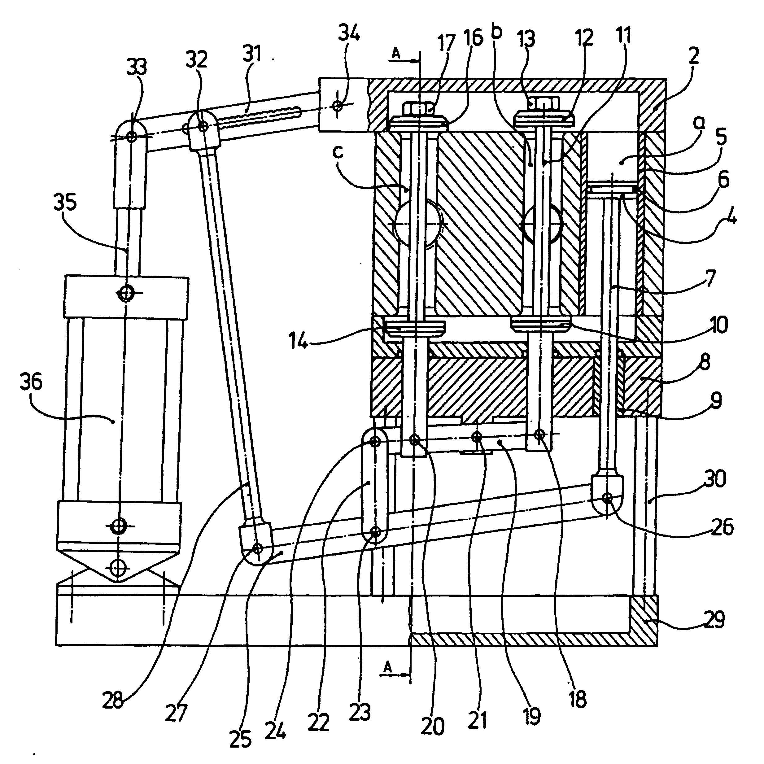
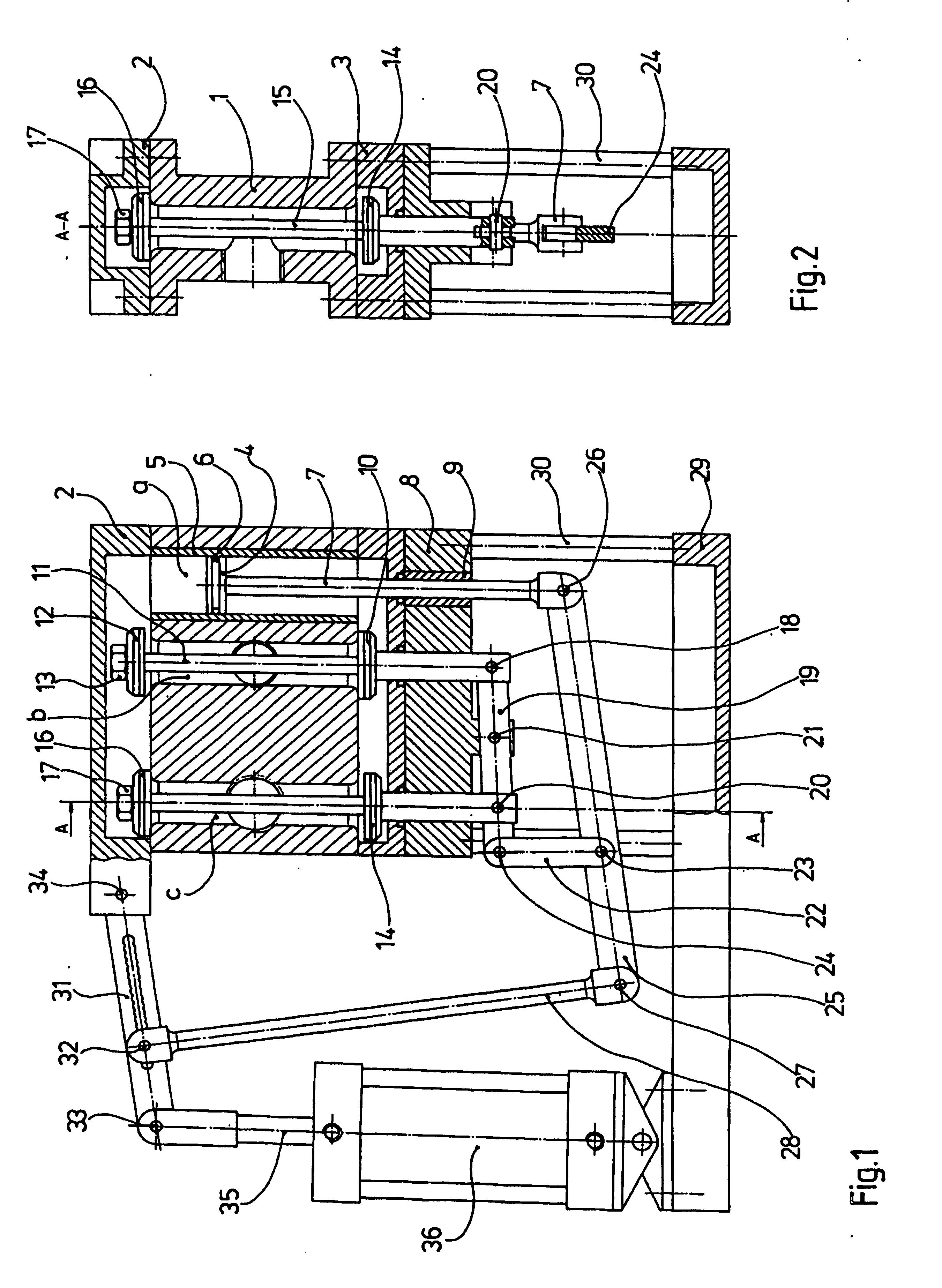
[0011] A pump casing 1, 2, 3 is illustrated in FIG. 1 with a pump cylinder 5 in which a piston pump 4 that is sealed with an O-Ring 6 is driven by a piston rod 7. The piston, sealed by an O-Ring 6 and a gasket 9 rod, pierces the pump casing 3 and the valve lid 8 with its end that faces away from the pump piston 4 and is connected at its end by a compensator 19 whose end is elongated and movably connects the valve rods 11, 15 to the conveying lever 25 through a plate 22. The conveying lever 25 pivots with anti-friction bushes 23, 26, 27, and is connected to the propelling lever 31 by a propelling rod 28. The propelling rod 31 is dissected in the middle so that the conveying lever 25 can be modified using a removable bolt 32 at its point of application. The pump piston's 4 stroke can thus be increased or reduced. The propelling lever 31 is connected in joints at one end to the pump lid 2 and with its other end to the piston rod 35 by bolts 33, 34. The piston rod 35 protrudes from a pn...


PUM


Abstract

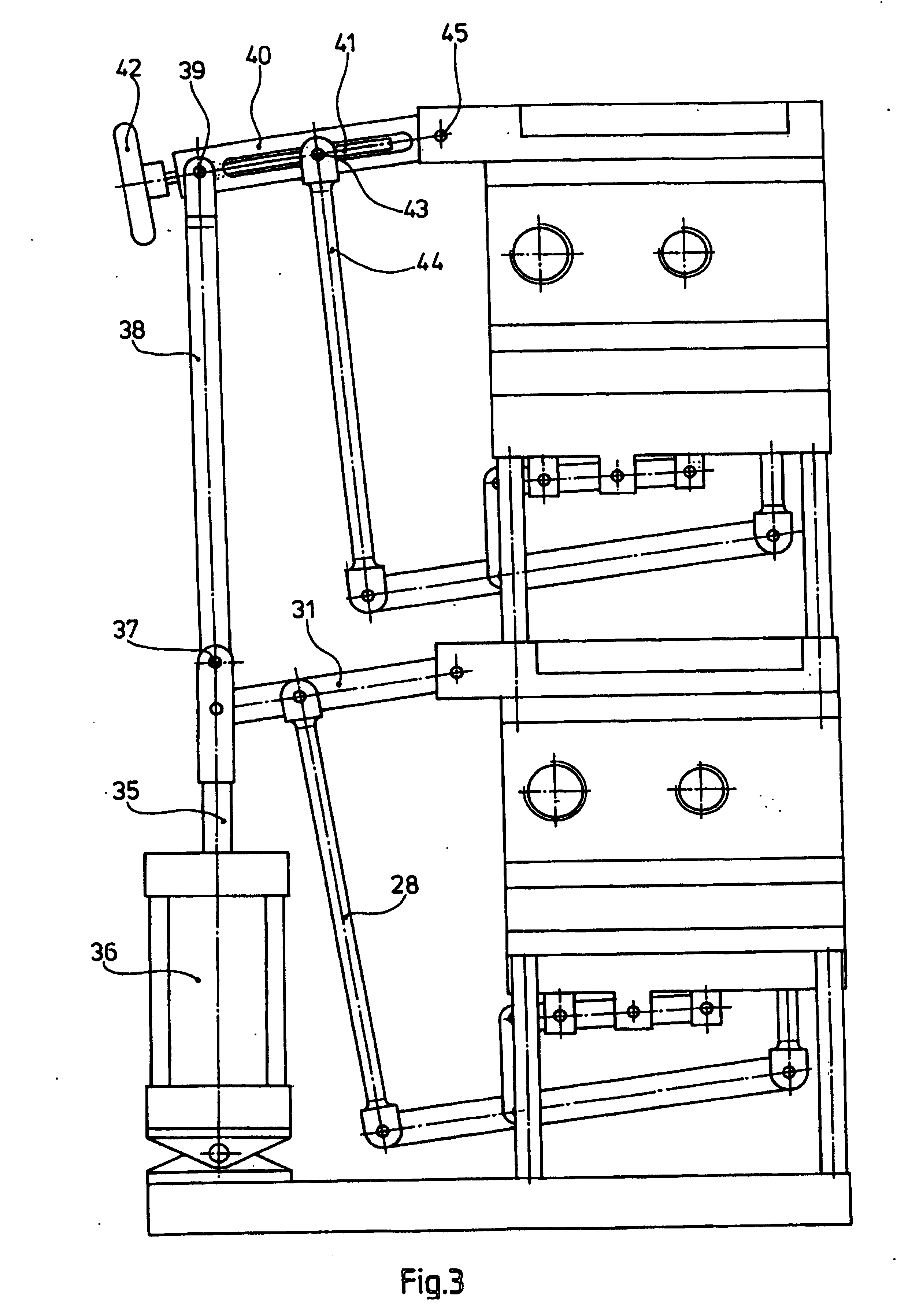
The invention relates to a piston pump whose piston (4), via its upper and lower piston faces, delimits the working space inside the pump cylinder (5) on both sides. The working space (c) is joined via a lever system (19, 22, 25, 28, 31) to two force-guided inlet valves (14, 16) and two force-guided outlet valves (10, 12) that each alternately open and close for filling or discharging the working volume upon reaching both final positions of the piston. An additional working volume, which is reduced by the volume portion of the piston rod, is obtained by the piston being acted upon twice per working stroke as described by the invention thus nearly doubling the efficiency and resulting in a delivery flow with few pulsations. A small residual pulsation remains only from the short period of time during which the valves change from open to closed upon reaching both end positions of the piston inside the cylinder. According to the invention, the design of the piston pump makes it possible for two or more piston pumps to be synchronously operated by coupling their drive levers (31, 40) to a common piston rod (35) and that, in doing this, different stroke lengths can be set by modifying the lever ratios.

Description

CROSS REFERENCE TO RELATED APPLICATIONS [0001] This is a 371 national phase application of International Application No. PCT / CH2004 / 000327 filed 01 Jun. 2004, which claims priority to Swiss Application Number 1169 / 03 filed 02 Jul. 2003, the contents of which are incorporated herein by reference.FIELD OF THE INVENTION [0002] The invention is with regard to a piston pump with a pump casing and a piston that narrows the working chamber in a pump cylinder through an elevating motion, in accordance with the preamble of patent claim 1. The invention preferably deals with a piston pump to convey or meter fluid media of the most varied nature. BACKGROUND OF THE INVENTION [0003] Piston pumps are generally established in a multiplicity of design versions and serve the most varied conveying or driving requirements (hydraulics). Piston pumps established in process engineering utilize only one front surface of the piston to fill and eject the pump medium. This results in unwanted pulsation which...

Claims


Application Information

Patent Timeline
Patent Type & Authority Applications(United States)
IPC IPC(8): F04B7/00
CPCF04B7/0053
Inventor WINIGER, GERHARD
Owner WINIGER GERHARD
Learn More