Eureka AIR delivers breakthrough ideas for toughest innovation challenges, trusted by R&D personnel around the world.

Evaporation method and evaporator

Inactive Publication Date: 2006-07-20
M WATANABE CO LTD
View PDF1 Cites 0 Cited by
  • Summary
  • Abstract
  • Description
  • Claims
  • Application Information

AI Technical Summary

Benefits of technology

[0009] The present inventors eagerly explored a factor of scattering of fine particles in a film in the prior art.
[0010] As a result, they assumed that a raw material solution which is sheared by a carrier gas and contained in the form of mist or steam having a particle diameter of 1 μm or below in the carrier gas is not gasified even in a vaporization chamber for some reason, and fine particles are not vaporized, but introduced into a film formation chamber as they are and then solidified.
[0011] Based on such an assumption, when they conducted various kinds of experiments while changing many conditions existing in vaporization and film formation in many ways, they discovered that using a heated carrier gas as the carrier gas can greatly reduce the number of the fine particles.
[0012] That is, in the present invention, the heated carrier gas is used as the carrier gas, and the fine particles in a film can be thereby greatly reduced.
[0013] Although its detailed reason is not clear, it can be considered that, when a raw material solution is introduced into the heated carrier gas, the raw material solution is atomized and instantaneously gasified.
[0014] As means for introducing the raw material into the carrier gas for atomization, arbitrary means can be used.

Problems solved by technology

Under the present situation, however, there are few devices which can maintain a concentration of a vaporized raw material constant and continuously and stably operate without clogging a vaporizer.
Further, in this technology, the carrier gas is not heated by cooling a supply passage and a gas passage for the raw material solution.
However, when vaporization and film formation were carried out by using this technology, it was found that fine particles of approximately 1 μm are scattered in a formed film.

Method used


Image

  • Evaporation method and evaporator
  • Evaporation method and evaporator

Examples


embodiment 1

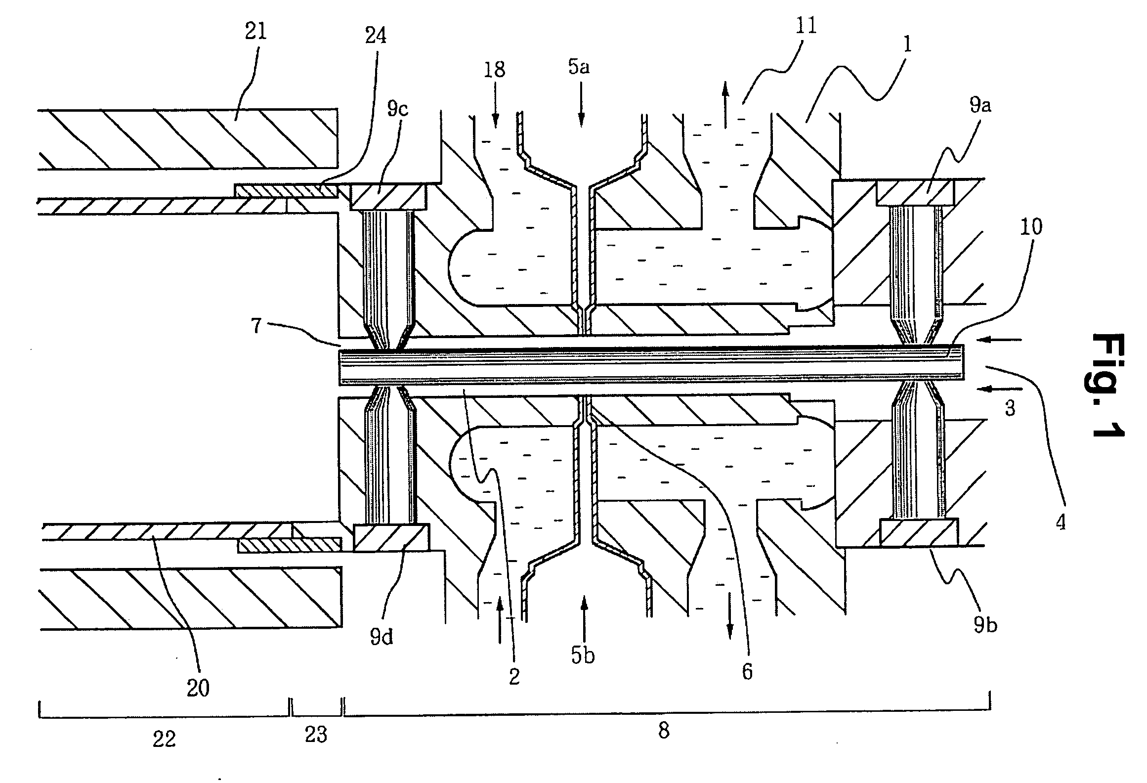
[0044] In this example, formation of an SBT film was carried out. An apparatus used is an apparatus shown in FIG. 1.

[0045] A raw material concentration of an organic metal complex abbreviated as (Sr / Ta2) in a raw material was set to 0.1 mol / L and its supply flow quantity was set to 0.02 mL / min.

[0046] On the other hand, a raw material concentration of a Bi organic metal complex was set to 0.2 mol / L, and its supply flow quantity was set to 0.02 mL / min.

[0047] As a solvent, n-Hexane was used to manufacture a raw material solution. Its supply quantity was set to 0.2 mL / min with respect to each raw material flow quantity.

[0048] On the other hand, as a carrier gas, a material obtained by mixing oxygen in an Ar gas was used.

[0049] The carrier gas was heated to 200° C. before being introduced into a passage. It is to be noted that its flow quantity was set to 210 mL / min.

[0050] It is to be noted that a supply passage of the raw material solution and a gas passage were cooled.

[0051] Und...

embodiment 2

[0054] In this example, a film was formed while changing a heating temperature of a carrier gas to 50° C., 100° C., 150° C., 200° C., 250° C. and 300° C.

[0055] In case of 50° C., the number of fine particles was smaller than that in Comparative Example 1. The number of fine particles was rapidly reduced from 100° C., and it became the smallest number at 200° C. At 300° C., the number of fine particles was 1 / 30 or below as compared with the comparative example.


PUM

PropertyMeasurementUnit
Temperatureaaaaaaaaaa
Diameteraaaaaaaaaa

Abstract

A vaporization method and a vaporizer capable of greatly reducing the number of fine particles scattered in a film after film formation. A raw material solution is brought into contact with a heated carrier gas and carried to a subsequent step. The vaporizer includes: a vaporization chamber; a carrier gas passage communicating with the vaporization chamber; a raw material solution lead-in port through which the raw material solution is led into the passage; and elements for heating the carrier gas.

Description

TECHNICAL FIELD [0001] The present invention relates to a vaporization method and a vaporizer which can perform atomization and vaporizing decomposition of a liquid raw material without reducing a temperature of an air current in a high-temperature region or a flow path maintained at a high temperature of, e.g., an MOCVD apparatus. BACKGROUND ART [0002] Patent Reference 1: Japanese Patent Application Laid-open No. 2000-216150. As one of devices crucial for semiconductor device manufacture, there is a CVD apparatus. Most of reaction chemical species supplied to this CVD apparatus are gases. However, a raw material obtained by solving an organic metal complex in an organic solvent must be used depending on a type of a thin film to be manufactured. This example is production of a ferroelectric thin film or the like by an MOCVD apparatus. In this case, a raw material must be transported and atomized by appropriate devices in order to prepare raw material vapor. Under the present situati...

Claims


Application Information

Patent Timeline
IPC IPC(8): H01L21/44C23C16/448H01L21/31
CPCC23C16/4481
Inventor TODA, MASAYUKIKUSUHARA, MASAKI
Owner M WATANABE CO LTD
Why Eureka
Eureka Blog
Learn More