
Voltage regulator with bypass mode

a voltage regulator and bypass mode technology, applied in the direction of electric variable regulation, process and machine control, instruments, etc., can solve the problems of low power supply requirements in each successive generation of transistor technology, lower power supply requirements of newer semiconductor process not always compatible with legacy host devices, and low cost, etc., to achieve broad applicability and small cost

Active Publication Date: 2006-07-27
SANDISK TECH LLC
View PDF31 Cites 46 Cited by
  • Summary
  • Abstract
  • Description
  • Claims
  • Application Information

AI Technical Summary

Benefits of technology

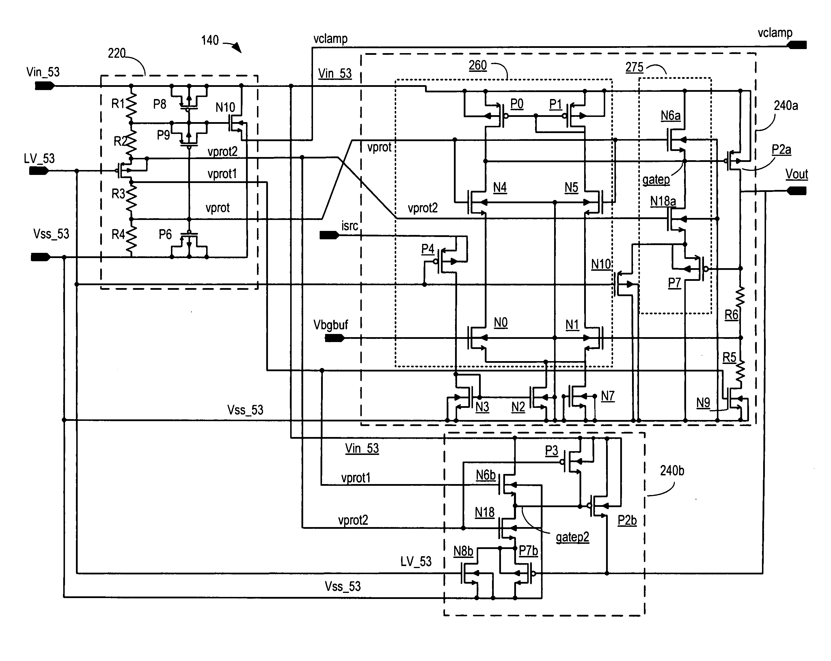
[0061] Hence, all elements of the circuit of the present invention are protected from having voltages exceeding their maximum rated voltages either in a punch-through phase, or in a configuration stressing the gate to drain or gate to source coupling of the devices. In this manner, devices will not be damaged.
[0062] The invention provides the advantage that the technology which is utilized to fabricate the semiconductor devices in the peripheral device being manufactured for use with a host computer system can be utilized to construct the voltage regulator. Previously, were a voltage regulator requiring a step-down from, for example, 5 volts to 3 volts to be utilized, the voltage regulator would use 5 volt

Problems solved by technology

Lower power devices generally translate into lower costs due to decreases in circuit size and power consumption.
This in turn has led to lower power supply requirements in each successive generation of transistor technology.
The lower power requirements of newer semiconductor processes are not always compatible with legacy host devices.
Generally, however, this is not possible, since the input load to the regulator can damage lower voltage devices.

Method used


Image

  • Voltage regulator with bypass mode
  • Voltage regulator with bypass mode
  • Voltage regulator with bypass mode

Examples


Embodiment Construction

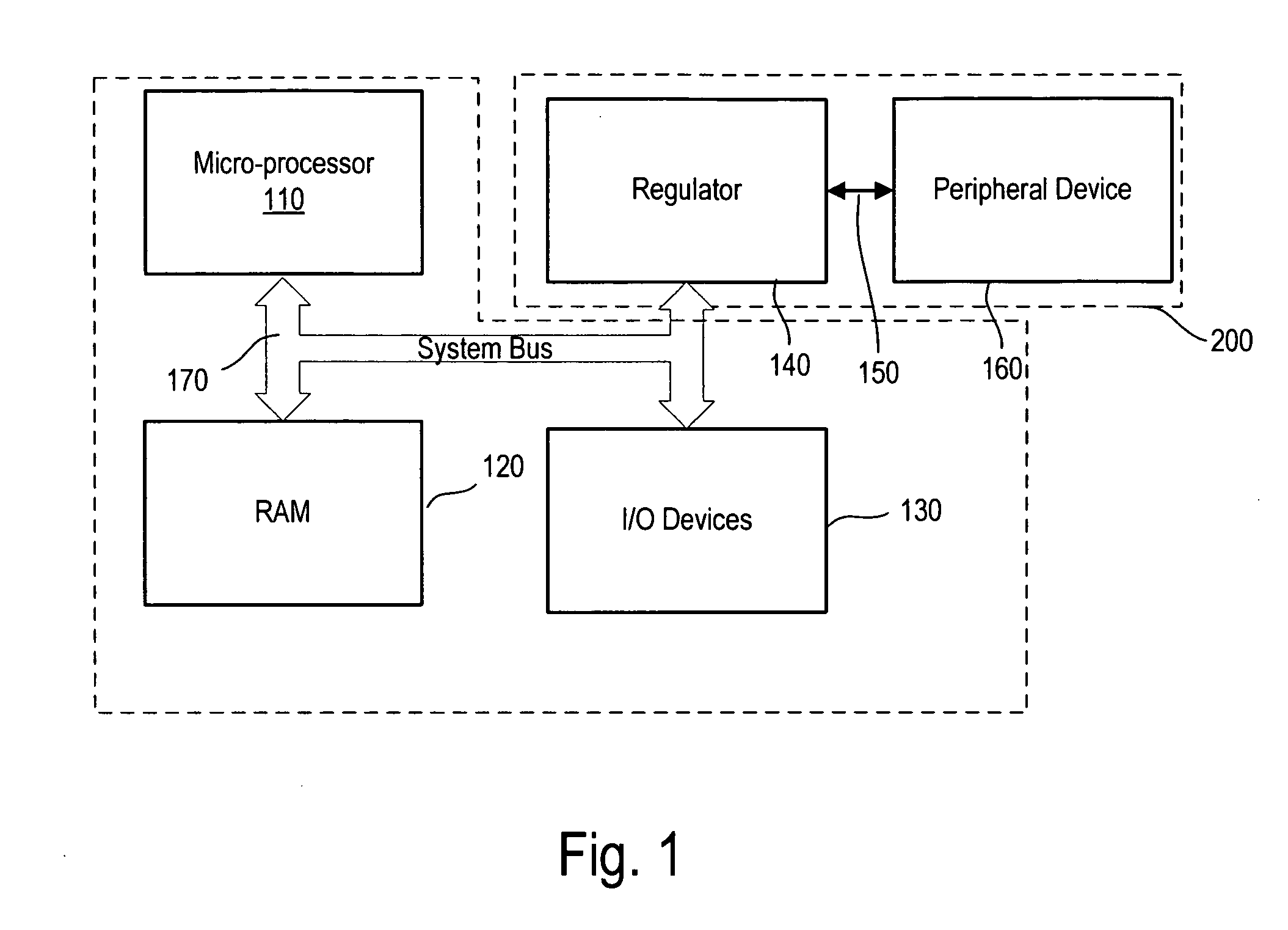
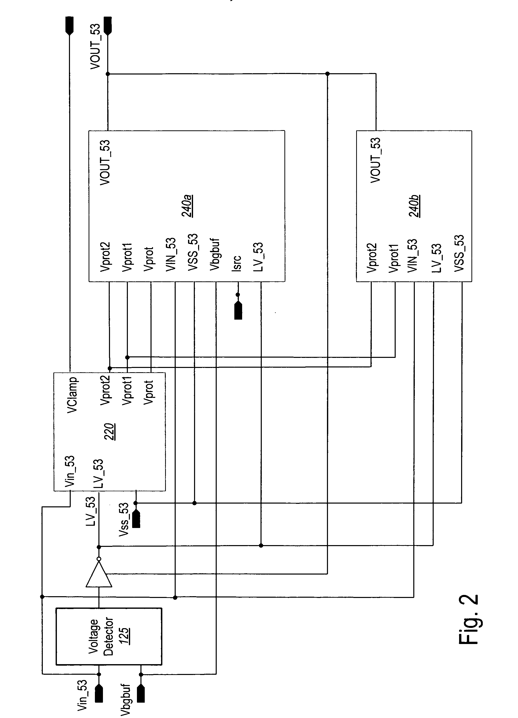
[0023] The invention provides a regulated voltage for operating a device coupled to a host when the host supply exceeds that necessary device operation, and a bypass mode, allowing the supply to pass to the device directly when the supply voltage is sufficient to power the device. The invention is implemented with transistors or other devices which are designed to operate at maximum rated voltages lower than the potential maximum supply voltage of the host. The invention ensures that the potentially higher-than-necessary host supply voltages do not damage the peripheral or the voltage regulator.

[0024] In one embodiment, the invention is suitable for use with a non-volatile memory system. However, the invention has myriad uses not limited to memory systems. The system may be utilized with any number of types of host devices such as cellular telephones, digital cameras, personal digital assistants, mobile computing devices, non-mobile computing devices and other devices. One typical ...


PUM


Abstract

A step down voltage regulator with bypass comprised of devices designed to operate over a maximum rated voltage lower than a supply voltage. The regulator includes an output regulation device coupled to the supply voltage and an output. An output device protection circuit is provided which is responsive to the supply voltage and the output to ensure that the maximum rated voltage of the output regulation device is not exceeded. A bypass circuit having a bypass output device and being coupled to the supply voltage is provided with a protection circuit. The output regulation devices comprise p-channel transistors, and may have an operating maximum rated voltage in a range of 2.7-3.6 volts with the supply voltage is in a range of 4.4-5.25 volts, or 2.9-3.5 volts.

Description

BACKGROUND OF THE INVENTION [0001] 1. Field of the Invention [0002] The present invention is directed to voltage regulation in multi-voltage supply applications, and in particular, for peripheral devices such as memory systems. [0003] 2. Description of the Related Art [0004] Advances in integrated circuit (IC) technology often relate to decreasing the size and operating voltages of devices used to fabricate circuitry. Lower power devices generally translate into lower costs due to decreases in circuit size and power consumption. Currently, low-voltage integrated circuits having transistors operating in the three-volt range and lower are highly desirable. The three-volt ICs are gradually replacing the standard five-volt ICs due to their higher speed and higher integration densities. Moreover, the three-volt ICs consume less power than the traditional five-volt ICs. In battery operated devices, such as portable telephones and lap-top computers, low-voltage integrated circuits allow th...

Claims


Application Information

Patent Timeline
IPC IPC(8): G05F1/40G05F1/618
CPCG11C5/147G11C29/02G11C29/021G11C29/028G11C16/30G11C16/26
Inventor WANG, YONGLIANGPASTERNAK, JOHN
Owner SANDISK TECH LLC
Learn More