X-ray generator and x-ray ct apparatus comprising same

a technology of x-ray generator and ct apparatus, which is applied in the direction of x-ray apparatus, electrical apparatus, etc., can solve the problems of unbalance between, large apparatus, and large obstacles, and achieve the effect of reducing both unbalance voltage and increasing the reduction

Inactive Publication Date: 2006-07-27
HITACHI MEDICAL CORP
View PDF2 Cites 27 Cited by
  • Summary
  • Abstract
  • Description
  • Claims
  • Application Information

AI Technical Summary

Benefits of technology

[0023] Further, if it is possible to reduce both the unbalance voltage due to difference in the circuit impedance and the unbalance voltage due to difference in the load impedance, the reduction effect is increa

Problems solved by technology

However, in the neutral grounding system, unbalance occurs between first DC high voltage Va and second DC high voltage Vk in some cases, and (1) and (2) listed below are the main reasons:
However, because a voltage larger than the rating is applied between the anode and the earth or between the cathode and the earth when the above mentioned unbalance voltage occurs and becomes large, the withstand voltage not only of the X-ray tube but also of the high voltage transformer, the high voltage rectifier, and high voltage parts attaching thereto has to be set

Method used


Image

  • X-ray generator and x-ray ct apparatus comprising same
  • X-ray generator and x-ray ct apparatus comprising same
  • X-ray generator and x-ray ct apparatus comprising same

Examples


embodiment 1

[0046] In this embodiment, an X-ray high voltage device which can remove the unbalance voltage due to (1) difference in impedance of a high voltage transformer mentioned in the section of the background technique will be described.

[0047] The reason of generation of the difference between Va and Vk (hereinafter referred to as “unbalance voltage”) due to the difference in impedance of the high voltage transformer mentioned at (1) will be analyzed, then solving means will be subsequently described. FIG. 9 shows an X-ray generator using a metal X-ray tube. In this high voltage transformer 3, because voltage difference between secondary windings 3c and 3d on a high voltage side and primary windings 3a and 3b on a low voltage side is very large, primary windings 3a and 3b and secondary windings 3c and 3d are detached at a predetermined distance and an insulator is inserted therebetween. A part of generated magnetic flux passes through between primary windings 3a and 3b and secondary wind...

embodiment 2

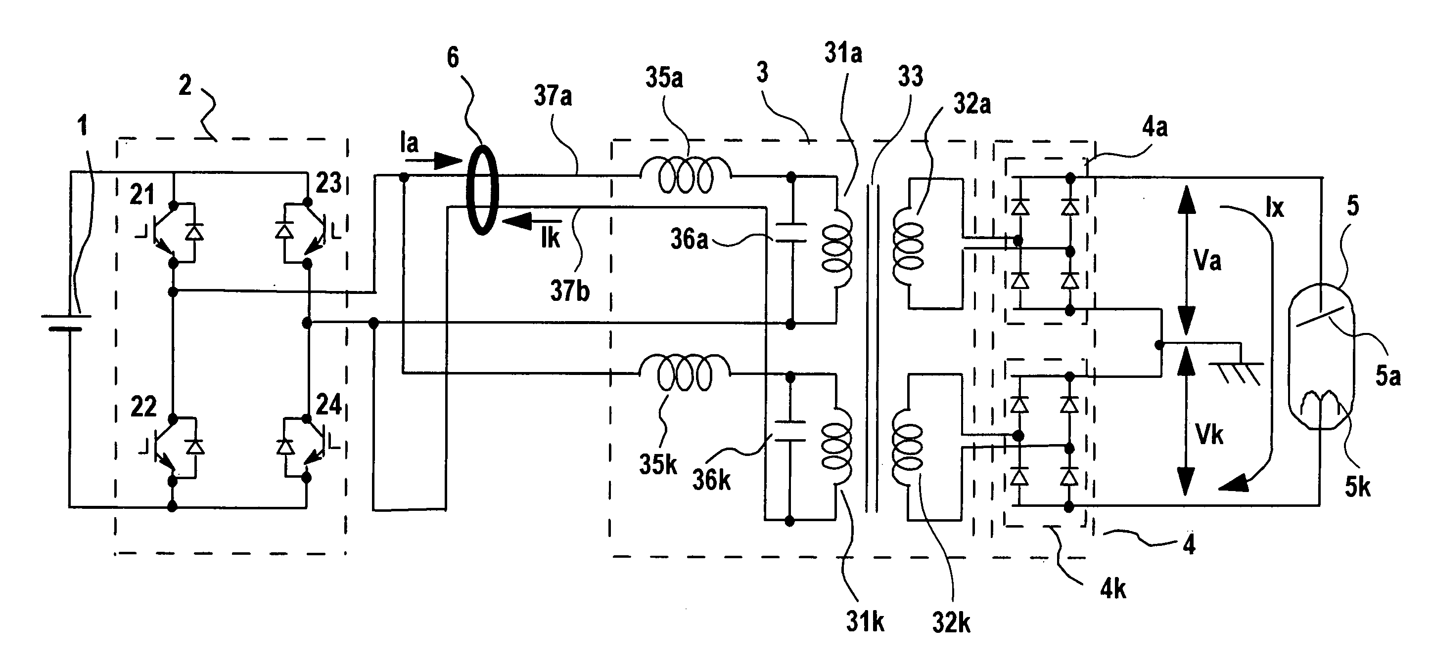
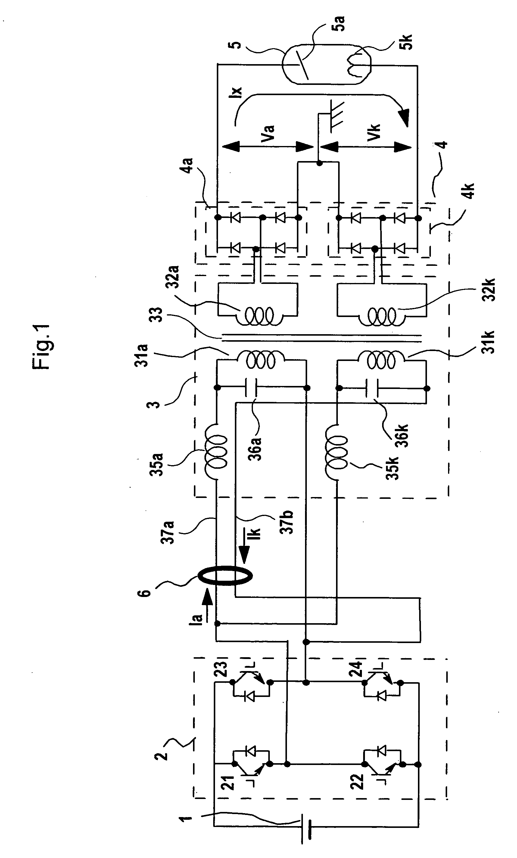
[0083] In this embodiment, an X-ray high voltage device will be described in which the unbalance voltage due to (1) the difference in impedance of high voltage transformer described in the section of the background technique and in Embodiment 1 can be removed. FIG. 3 is a schematic diagram of an inverter-type X-ray high voltage device according to Embodiment 2, a main object of which is to remove the unbalance voltage generated due to impedance difference in the high voltage transformer. Similarly to Embodiment 1, the X-ray tube according to Embodiment 2 may be either a glass X-ray tube or a metal X-ray tube. FIG. 3 shows the case of the glass X-ray tube as in FIG. 1.

[0084] According to Embodiment 2, the secondary windings of high voltage transformer 3 and high voltage rectifier 4 are further divided than in Embodiment 1 shown in FIG. 1, wherein first secondary windings of the high voltage transformer is divided into 32a1 and 32a2, second secondary windings 32k is divided into 32k1...

embodiment 3

[0092] In Embodiment 3, an X-ray high voltage device which can remove the unbalance voltage due to both the difference in impedance of the high voltage transformer described at (1) and the difference in load impedance described at (2) will be described. Since analysis of (1) generation of impedance of the high voltage transformer is described in Embodiment 1, the reason of (2) generation of the difference between Va and Vk (hereinafter referred to as “unbalance voltage”) due to difference in impedance of the high voltage transformer will be analyzed and means for solving (1) and (2) according to this embodiment will be subsequently described.

[0093] The unbalance voltage due to (2) the difference in load impedance is generated in an inverter-type X-ray high voltage device using a metal X-ray tube, a part of a container of which is made of metal and grounded to the earth. As shown in FIG. 12, first high voltage rectifier 4a is connected with anode 5a ′ of X-ray tube 5′ and second hig...


PUM


Abstract

In an X-ray generating device of the neutral grounding system, to remove an unbalance voltage generated due to difference in impedance of parallel transformer coils of the high voltage transformer and particularly an unbalance voltage involved with difference in impedance above and below the neutral points generated in a metal X-ray tube, a plurality of currents flowing in opposite directions through primary windings of the parallel transformer coils in the high voltage transformer are passed through by or wound around a common toroidal coil or wound around an outer circumference of the toroidal coil at a predetermined ratio of winding number, and the unbalance voltage occurring to the secondary side is cancelled by changing primary current with magnetic behavior.

Description

TECHNICAL FIELD [0001] The present invention relates to an X-ray generating device and an X-ray CT apparatus using it, more particularly to a technique with which stability, and reliability of the device can be maintained by equalizing voltage between an anode and an earth and that between a cathode and the earth of an X-ray tube in a miniaturized and lightweighted X-ray generating device. Further, it relates to an X-ray CT apparatus which can realize rapid scan by mounting this X-ray generating device on a scanner of the X-ray CT apparatus. BACKGROUND OF THE INVENTION [0002] An image diagnostic apparatus using X-rays is designed to radiate X-rays generated from an X-ray generating device to an object to be examined, and detect and image a dose of X-rays which passes through the object. To generate X-rays from an X-ray tube device, DC high voltage is applied between an anode and a cathode of the X-ray tube device, and thermal electrons generated by heating the cathode to a high temp...

Claims


Application Information

Patent Timeline
IPC IPC(8): H05G1/34H05G1/50H05G1/12H05G1/10
CPCH05G1/10
Inventor TAKAHASHI, JUNDOMOTO, TAKUYATAKANO, HIROSHI
Owner HITACHI MEDICAL CORP
Why Eureka
Try Eureka