
Methods of freezeout prevention and temperature control for very low temperature mixed refrigerant systems

Inactive Publication Date: 2006-08-03
EDWARDS VACUUM LLC
View PDF93 Cites 44 Cited by
  • Summary
  • Abstract
  • Description
  • Claims
  • Application Information

AI Technical Summary

Benefits of technology

[0030] An advantage of the present invention is that methods to control the temperature and / or prevent freezeout of the refrigerant mixture are disclosed for use in very low temperature refrigeration systems.
[0031] A further advantage of this invention is the stability of systems utilizing the disclosed methods over a range of operating [cool, defrost, standby or bakeout] modes.
[0032] Yet another advantage of the invention is the ability to operate the VLTMRS near the freezeout point of the refrigerant mixture.

Problems solved by technology

The longer the overall defrost cycle and subsequent resumption of producing very low temperature temperatures, the lower the throughput of the manufacturing system.
Exposing the refrigerant and any residual compressor oil resident in the element to such high temperatures when no refrigerant flow is occurring through the element presents the risk of overheating the resident refrigerant with consequent decomposition of the refrigerant and / or the oil.
Conventional refrigeration systems have historically utilized chlorinated refrigerants, which have been determined to be detrimental to the environment and are known to contribute to ozone depletion.
Thus, increasingly restrictive environmental regulations have driven the refrigeration industry away from chlorinated fluorocarbons (CFCs) to hydrochlorofluorocarbons (HCFCs).
The oils used in very low temperature systems using chlorinated refrigerants had good miscibility with the warmer boiling components that are capable of being liquefied at room temperature when pressurized.
Colder boiling HFC refrigerants such as R-23 are not miscible with these oils and do not readily liquefy until they encounter colder parts of the refrigeration process.
This immiscibility causes the compressor oil to separate and freezeout, which in turn leads to system failure due to blocked tubes, strainers, valves or throttle devices.
Unfortunately, ethane is flammable, which can limit customer acceptance and can invoke additional requirements for system controls, installation requirements and cost.
If a freezeout condition occurs, the suction pressure tends to drop even further creating positive feedback and further reducing the temperature, causing even more freezeout.
As mentioned above, the use of hydrocarbons is undesirable due to their flammability.
However, elimination of flammable components causes additional difficulties in the management of freezeout since the HFC refrigerants that can be used instead of flammable hydrocarbon refrigerants typically have warmer freezing points.
Typically freezeout occurs when the external thermal load on the refrigeration system becomes very low.
This in turn results in colder temperatures of the expanded refrigerant entering the subcooler.
Since margin must be provided relative to such a condition as freezeout, the resulting refrigeration design will often be limited as the overall system is designed to never encounter a freezeout condition.
Another challenge when using hydrofluorocarbons (HFCs) as refrigerants is that these refrigerants are immiscible in alkylbenzene oil and therefore, a polyolester (POE) (1998 ASHRAE Refrigeration Handbook, chapter 7, page 7.4, American Society of Heating, Refrigeration and Air Conditioning Engineers) compressor oil is used to be compatible with the HFC refrigerants.
Although this method proved effective for the systems it was employed on, it was not able to provide the required control.
This is because, using a valve to increase the pressure of the upstream low-pressure refrigerant to prevent freezeout reduced the refrigeration performance of the system.
The disclosed valve has to be adjusted manually, and it is not practical to adjust it manually as needed for the different modes of operation (i.e. cool, defrost, standby and bakeout).
Therefore, control methods from conventional single refrigerant or mixtures with behavior similar to a single refrigerant, cannot be applied to a VLTMRS in the same manner as conventional systems due to this difference in temperature-pressure correspondence.
Also, Forrest et al. does not make use of a discharge line oil separator.
It is known that compressor oil in the VLTMRS can lead to blocking of flow passages and lead to the types of symptoms that Forrest et al. seeks to avoid.

Method used


Image

  • Methods of freezeout prevention and temperature control for very low temperature mixed refrigerant systems
  • Methods of freezeout prevention and temperature control for very low temperature mixed refrigerant systems
  • Methods of freezeout prevention and temperature control for very low temperature mixed refrigerant systems

Examples


first embodiment

[0144] Because the temperature control embodiment of FIG. 5 uses the same bypass circuit through valve 218 and FMD 216 as in FIG. 2, these embodiments are called the “first embodiment,” herein.

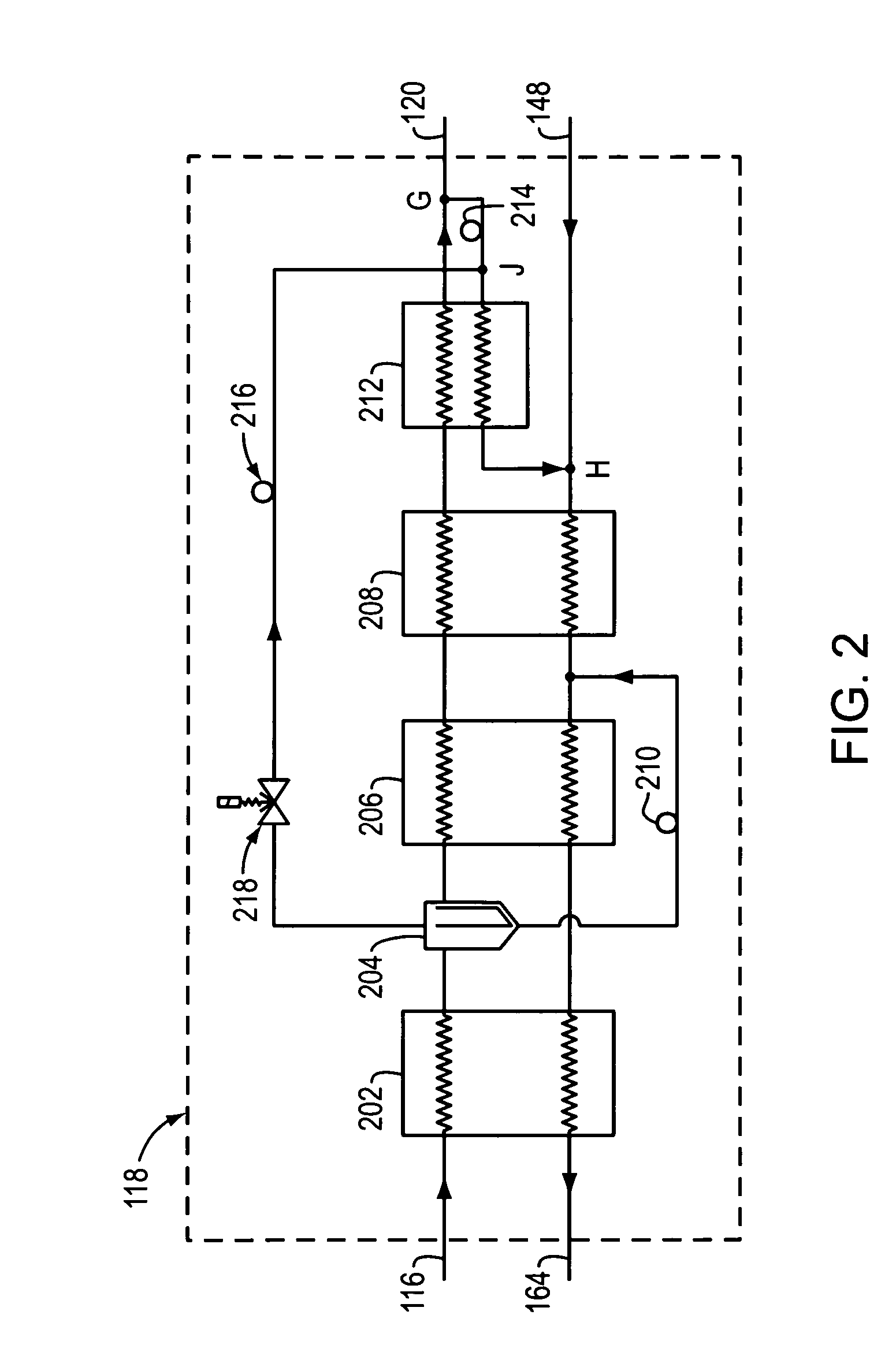
[0145]FIG. 3 illustrates a second embodiment of the invention. In this embodiment a different method of controlling temperature and / or preventing freezeout is described. The coldest liquid refrigerant at node G is split to a third branch that feeds valve 318 and FMD 316. The exiting flow from FMD 316 mixes at node H with flows exiting from the subcooler 212 and the return refrigerant stream 148. As in the first embodiment the goal is to eliminate the potential for freezeout, and / or to control temperature for other purposes.

second embodiment

[0146] In the second embodiment, temperature is controlled and / or freezeout is prevented or temperature controlled by keeping a lower flow rate of refrigerant through the low-pressure side of subcooler 212 than through the high-pressure side of subcooler 212. This causes the high-pressure flow exiting subcooler 212 to be warmer. Adjusting the ratio of flow that bypasses directly from node G to H causes varying degrees of warming of the refrigerant exiting the high-pressure side of subcooler 212 and consequently causes a warming of the expanded refrigerant entering the low-pressure side of subcooler 212. The more flow that is bypassed around the subcooler, the more temperature control effects are produced, for example producing warmer cold end temperatures.

[0147] In contrast, prior art systems did not use this method and had equal flows on both sides of the subcooler, when flow to the evaporator was turned off. This method worked well in systems with a basic defrost method when the F...

third embodiment

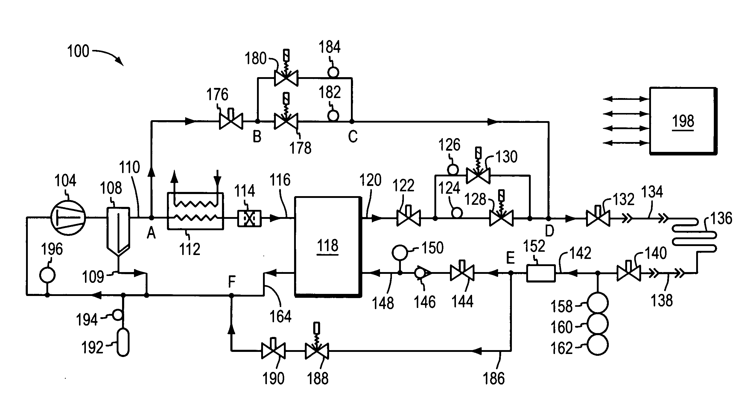
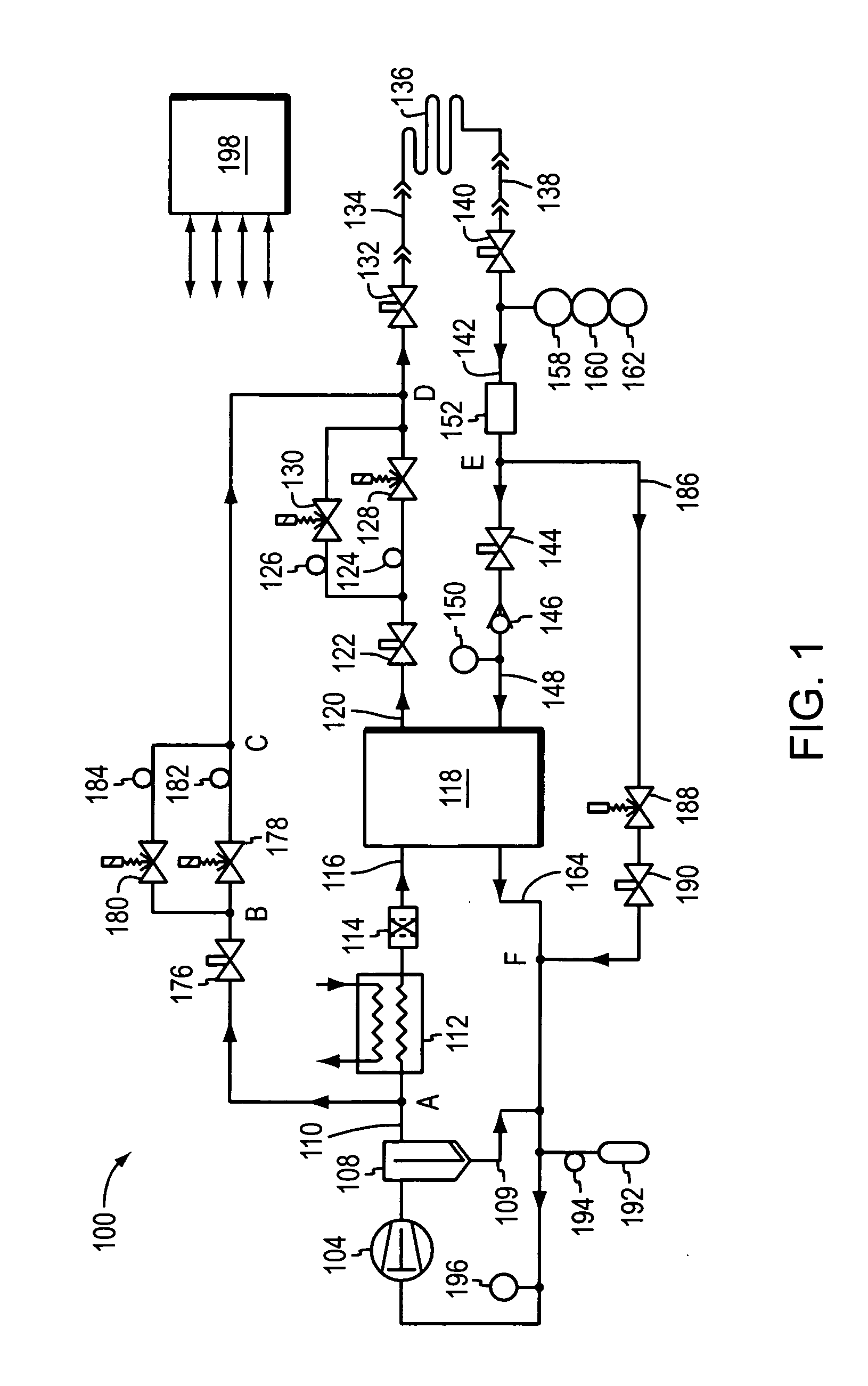
[0156] In the invention, FIG. 4 depicts another alternate method to provide temperature control and / or to manage refrigerant freezeout. In this case modifications are made to components typically located near the compressor. Typically these can be components that operate from room temperature to no colder than −40° C. This is shown as refrigeration system 200, which is modified from refrigeration system 100 by the addition of control valve 418 and FMD 416. This arrangement provides a means to bypass refrigerant flow from high pressure to low pressure and to bypass the refrigeration process 118.

[0157] This has a number of effects. Two of these effects, considered to be the most important, are a reduction in the flow rate through the refrigeration process and an increase in the low pressure of the refrigeration system. When a sufficient amount of flow is bypassed through these additional components, warming is elected, resulting in temperature control and / or freezeout prevention in th...


PUM


Abstract

Refrigerant freezeout is prevented, and temperature is controlled, by the use of a controlled bypass flow that causes a warming of the lowest temperature refrigerant in a refrigeration system that achieves very low temperatures by using a mixture of refrigerants comprising at least two refrigerants with boiling points that differ by at least 50° C. This control capability enables reliable operation of the very low temperature system.

Description

RELATED APPLICATIONS [0001] This application is a continuation-in-part of U.S. application Ser. No. 11 / 332,495, filed on Jan. 13, 2006, entitled “Methods of Freezeout Prevention for Very Low Temperature Mixed Refrigerant Systems,” which is a continuation of U.S. application Ser. No. 10 / 281,881, filed on Oct. 28, 2002, which claims the benefit of U.S. Provisional Application No. 60 / 335,460, filed on Oct. 26, 2001. The entire teachings of the above applications are incorporated herein by reference.FIELD OF THE INVENTION [0002] This invention relates to processes using throttle expansion of a refrigerant to create a refrigeration effect. BACKGROUND OF THE INVENTION [0003] Refrigeration systems have been in existence since the early 1900s, when reliable sealed refrigeration systems were developed. Since that time, improvements in refrigeration technology have proven their utility in both residential and industrial settings. In particular, low-temperature refrigeration systems currently ...

Claims


Application Information

Patent Timeline
IPC IPC(8): F25B41/00F25B49/00
CPCF25B9/006F25B40/00F25B47/006F25B47/022F25B2400/04F25B2400/13F25B2400/23F25B2600/2515F25B9/00F25B49/00
Inventor FLYNN, KEVIN P.BOIARSKI, MIKHAILPODTCHERNIAEV, OLEG
Owner EDWARDS VACUUM LLC
Features
  • Generate Ideas
  • Intellectual Property
  • Life Sciences
  • Materials
  • Tech Scout
  • Unparalleled Data Quality
  • Higher Quality Content
  • 60% Fewer Hallucinations
Learn More