Location virtualization in an RFID system

a virtualization and location technology, applied in the field of radio frequency identification systems, can solve the problems of limited life span of active tags, essentially unlimited life span, and conventional rfid systems described, and achieve the effect of increasing reliability

Active Publication Date: 2006-08-03
ODIN SOFTWARE INC +1
View PDF36 Cites 337 Cited by
  • Summary
  • Abstract
  • Description
  • Claims
  • Application Information

AI Technical Summary

Benefits of technology

[0019] In accordance with the present invention, a system and method is provided that can identify and track tagged merchandise, personnel, and other items and / or individuals within an RFID environment with increased reliability. The presently disclosed system and method can also be employed to determine locations of one or more tags within the environment.

Problems solved by technology

Because passive tags do not have a durable power source, they do not include active semiconductor circuitry and must therefore maintain data and state information statically within its embedded memory.
In addition, passive tags have an essentially unlimited life span, while the life span of active tags is typically limited by the lifetime of the internal battery, which in some implementations may be replaceable.
However, the conventional RFID systems described above have a number of drawbacks.
For an RFID system that includes a single RFID reader, the penetration ability of the reader is typically limited by the reader's maximum transmit power.
It may therefore be virtually impossible to infer the actual interrogation zone of the reader directly from the reader's transmission and reception settings and the transmission / reception capabilities of the tags.
Moreover, the interrogation zone of an RFID reader often fails to match the space that needs to be monitored in the RFID application.
In addition, the conventional RFID system employing a single RFID reader is generally incapable of determining the location and / or direction of a moving RFID tag with precision.
For example, in the event an RFID tag is attached to a forklift truck at a warehouse storage facility, a single RFID reader may be unable to determine whether the forklift is leaving or entering the facility at it passes the reader, which may be disposed at a dock bay.
Conventional RFID systems that employ multiple RFID readers also have drawbacks.
However, such dense deployments of RFID readers are problematic due to RF interference and potentially conflicting channel assignments of the readers.
Significant RF interference may also occur when readers operate on adjacent channels.
Even if multiple readers operate on channels sufficiently far apart to avoid reader-to-reader interference, reader-to-tag interference may still occur since RFID tags are broadband devices capable of receiving RF transmissions from more than one reader at a time, which can confuse the tag circuitry.
In addition, when multiple RFID readers are deployed within a conventional RFID system, the system is typically incapable of successfully coordinating the operation of the readers.
Further, each of the multiple readers is limited in time and frequency usage to the transaction paradigms typically employed by conventional standalone readers.
For example, each reader may only have access to its own information, and may therefore be unable to react to events detected by the other readers within the system.
As a result, the multiple readers are generally incapable of managing the large amount of potentially redundant information collected by the readers from the same group of tags within the same environment over an extended period of time.
Further, such conventional systems are generally unable to discriminate between significant events and essentially meaningless movements of items and / or individuals within the RFID environment.
Moreover, such conventional systems are generally incapable of keeping track of the various locations and functions of the many readers deployed within the environment, and assuring that all of the readers within the system are properly maintained and operational.

Method used


Image

  • Location virtualization in an RFID system
  • Location virtualization in an RFID system
  • Location virtualization in an RFID system

Examples


Embodiment Construction

[0055] The disclosure of U.S. Provisional Patent Application No. 60 / 592,933 filed Jul. 30, 2004 entitled ACCESSING RFID TAG DATA USING A READER ARRAY is incorporated herein by reference.

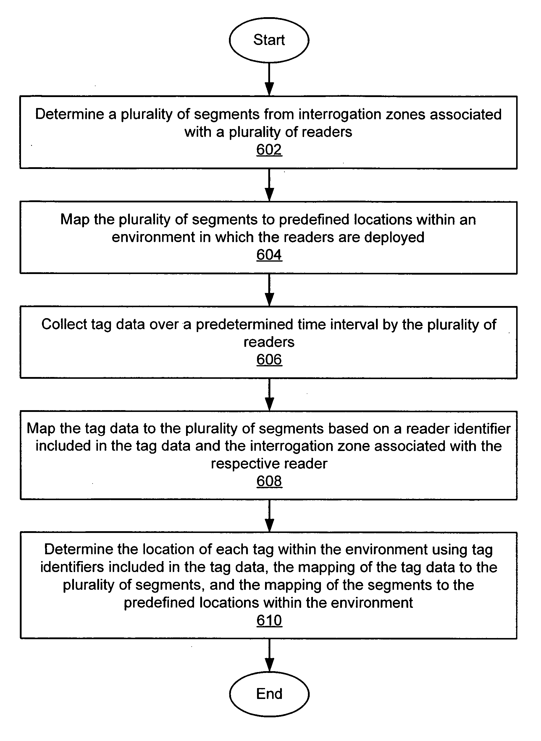
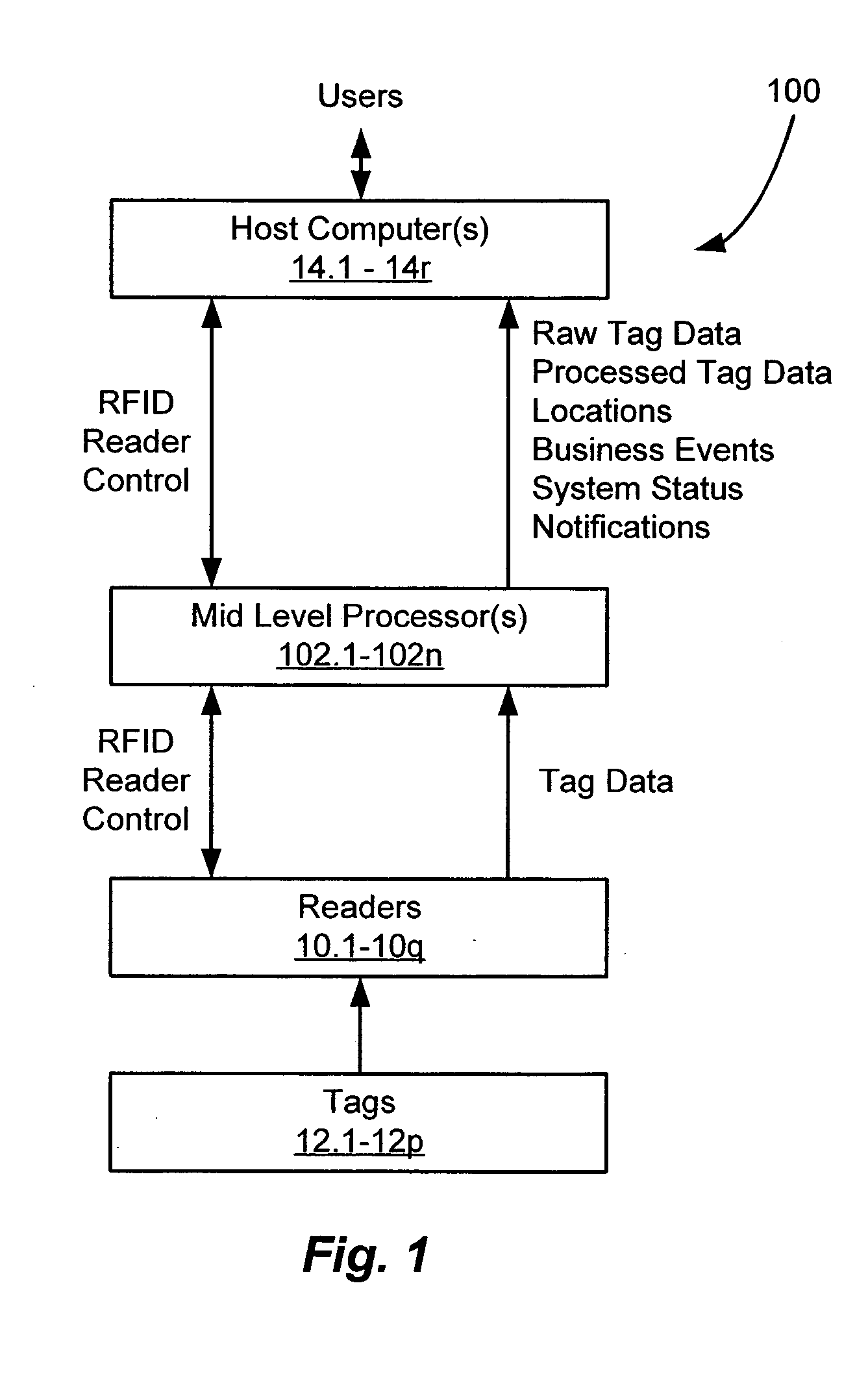
[0056] A system and method of accessing radio frequency identification (RFID) tag data is disclosed that provides enhanced coordination of multiple RFID readers with respect to frequency, time, space, and transmit power. The presently disclosed system employs at least one mid-level processing component and at least one host computer running client software applications. The mid-level processing component effectively transforms the operation of the RFID readers from an aggregated but essentially autonomous operating mode to a highly coordinated operating mode, in which the respective readers effectively function as elements of an RFID reader array. A system and method is also disclosed for determining locations of one or more tags within an RFID environment in which the plurality of readers is deploy...


PUM


Abstract

A system and method of determining locations of one or more RFID tags within an RFID environment. The system includes a plurality of RFID readers, each operative to transmit and receive RF signals for scanning a tag disposed within an RF coverage region associated with the reader, and for receiving tag data in response to the scanning of the tag. A plurality of sub-locations is determined within the environment, each corresponding to at least a portion of at least one of a plurality of RF coverage regions associated with the readers. The sub-locations are mapped to a plurality of predefined locations within the environment. A reader scans a tag, and receives tag scan data from the tag in response to the scanning of the tag. The tag scan data includes a tag identifier associated with the scanned tag. The tag scan data is mapped to the sub-locations based on the RF coverage region associated with the reader. The location of the scanned tag is then determined with reference to the predefined locations within the environment, based on the tag identifier included in the tag scan data, the mapping of the tag scan data to the sub-locations, and the mapping of the sub-locations to the predefined locations.

Description

CROSS REFERENCE TO RELATED APPLICATIONS [0001] This application claims benefit of U.S. Provisional Patent Application No. 60 / 592,933 filed Jul. 30, 2004 entitled ACCESSING RFID TAG DATA USING A READER ARRAY.STATEMENT REGARDING FEDERALLY SPONSORED RESEARCH OR DEVELOPMENT [0002] N / A BACKGROUND OF THE INVENTION [0003] The present invention relates generally to a radio frequency identification (RFID) system including a plurality of RFID readers, and more specifically to a system and method of determining locations of one or more RFID tags within an environment in which the plurality of readers is deployed. [0004] In recent years, radio frequency identification (RFID) systems have been employed in an ever increasing range of applications. For example, RFID systems have been used in supply chain management applications to identify and track merchandise throughout manufacture, warehouse storage, transportation, distribution, and retail sale. RFID systems have also been used in security app...

Claims


Application Information

Patent Timeline
Patent Type & Authority Applications(United States)
IPC IPC(8): H04Q5/22
CPCG01S5/0252G01S5/06G06K7/0008G06K7/10356G06K17/0029G06K2017/0045G06K2017/0048G06K2017/0051G01S5/02525
Inventor HUSAK, DAVID J.KRISHNA, PATTABHIRAMANSPREADBOROUGH, PETERFISCHER, JEFFREY H.
Owner ODIN SOFTWARE INC
Why Eureka
Try Eureka