
Caching For Volume Visualization

a volume visualization and volume technology, applied in the field of system for visualizing a three-dimensional (), can solve the problems of complex loop control structures for simultaneous processing of multiple rays and dependence on projection directions, and achieve the effects of fast processing of sub-bundle blocks, fast access to bundle blocks, and fast access to voxels

Inactive Publication Date: 2006-08-03
KONINKLIJKE PHILIPS ELECTRONICS NV
View PDF4 Cites 20 Cited by
  • Summary
  • Abstract
  • Description
  • Claims
  • Application Information

AI Technical Summary

Benefits of technology

[0013] a memory cache for temporarily storing part of the data set stored in the memory to provide faster access to data in the cache;
[0015] an output for providing pixel values of the 2D representation for rendering. In modern computer systems, the memory latency is large (˜50 ns) with respect to the processor cycle time (<1 ns). Cache latency is usually only a few processor cycles (˜5 ns). The discrepancy between process cycle time and memory access latency is expected to grow as processor cycle times continue to decrease at a rate significantly higher than the decrease in memory access latency. Workstations used for medical image display have about 1 Gbyte of memory, processors with cycle times less than 1 ns and cache memories of about 2 Mbyte. Common volume visualization techniques require in the order of 100 cycles per sample. For 50 ns memory and 1 ns cycle time the processor will be memory bandwidth limited when accessing memory more than twice per sample. For tri-linear interpolation, eight voxels must be accessed for each sample requiring eight memory accesses unless voxels are already available in the cache. Multi-slice CT volume data often consists of 1000 slices of 5122 16-bit voxels. This amounts to about 500 Mbytes of data and clearly does not fit entirely in cache memory. In the conventional processing per ray, voxels that are not in the cache are frequently accessed. Typically, a loaded voxel will be overwritten by a voxel required for one of the later samples along the ray. Since a voxel is usually required for several neighboring rays, the same voxel may be loaded into the cache repeatedly. In the system according to the invention, ray processing is organized in 3D blocks of samples such that all voxels contributing to the samples in the block are loaded into the cache. The size of the blocks and the addressing of voxels in memory are chosen such that this is possible. This enables avoiding repeatedly loading of the same voxels into cache thereby significantly increasing volume visualization performance.
[0017] According to the measure of the dependent claim 3, the same principle is applied at least two levels. The entire voxel set is divided into bundle blocks that fit into a level 2 cache. The bundle blocks are further sub-divided into sub-bundle blocks that fit into a level 1 cache of the processor. This results in faster access to the bundle block as a whole, compared to access to the main memory, and even faster access to voxels of the sub-bundle during the actual sampling. So, first a bundle block is determined and loaded into the second level cache. Sequentially sub-bundle blocks are determined, loaded in the first level cache and sampling is performed for samples within the sub-bundle block. Processing of the sub-bundle-block can be very fast. Voxels of a bundle-block may be required for several sub-bundle blocks (e.g. due to the interpolation extent, voxels near an edge of a sub-bundle block may be used for sampling of more than one sub-bundle block). By already being in the second level cache, those voxels can be loaded into the first level cache very fast.
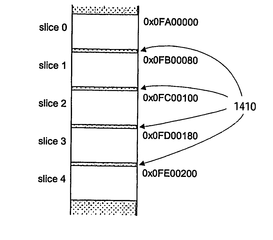
[0020] According to the measure of the dependent claim 6, a slice look-up table is used. This is an effective way of controlling storage of the slices in the memory.

Problems solved by technology

Furthermore, loop control structures for simultaneous processing of multiple rays become complex and dependent on the projection direction.

Method used


Image

  • Caching For Volume Visualization
  • Caching For Volume Visualization
  • Caching For Volume Visualization

Examples


Embodiment Construction

[0041] The system for visualizing volumes and a method of doing so will be described for medical applications. It will be appreciated that the system and method can also be applied to other applications as well, in general for inspection of the inner parts and structure of all objects which can be measured with a system, characterized by the fact that processing of the measurements results in a 3-dimensional dataset (3D array of measurements) representing a (part of the) volume of the object, and in which each data element or voxel relates to a particular position in the object and has a value which relates to one or more local properties of the object, for example for X-ray inspection of objects that can not be opened easily in the time available.

[0042]FIG. 8 shows a block diagram of the system according to the invention. The system may be implemented on a conventional computer system such as a workstation or high-performance personal computer. The system 800 includes an input 810...


PUM


Abstract

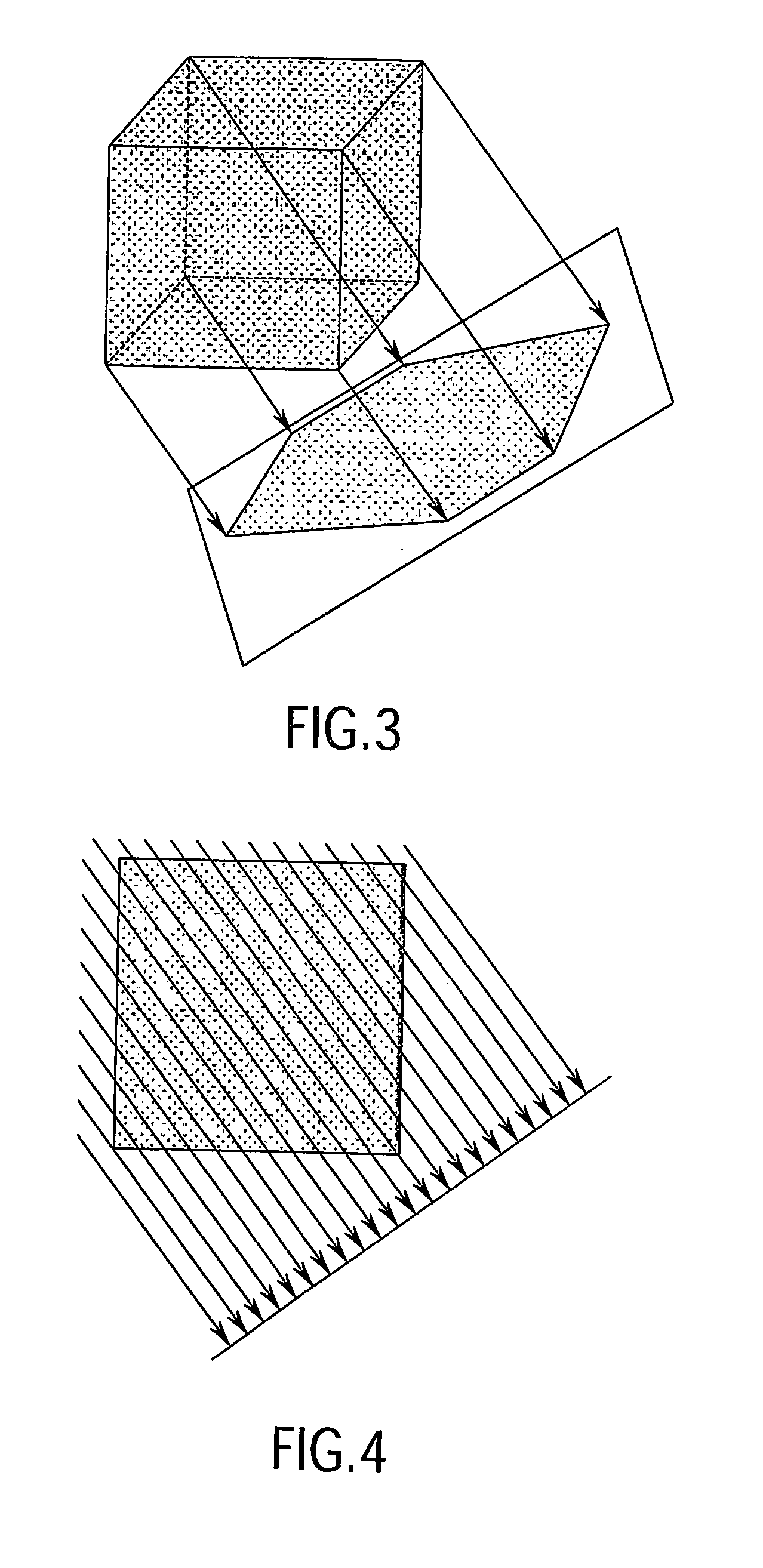
A system for visualizing a 3D volume, represented by a 3D data set stored in a memory (890) as contiguous 2D slices with successive depths. A memory cache 895 provides faster access to part of the data set. A processor 860 creates a 2D representation of the volume by casting an imaginary bundle of n1×n2parallel rays through the 3D volume onto a corresponding rectangle of n1×n2 pixels. Each time sequentially n3 samples are determined for each ray, giving a sequence of bundle blocks of each n1×n2×n3 samples. An interpolation function is used to determine a 3D set of voxels contributing to the bundle block. The size of the bundle block is chosen such that the determined set of voxels fits into the cache. The set of voxels is then sampled from the cache.

Description

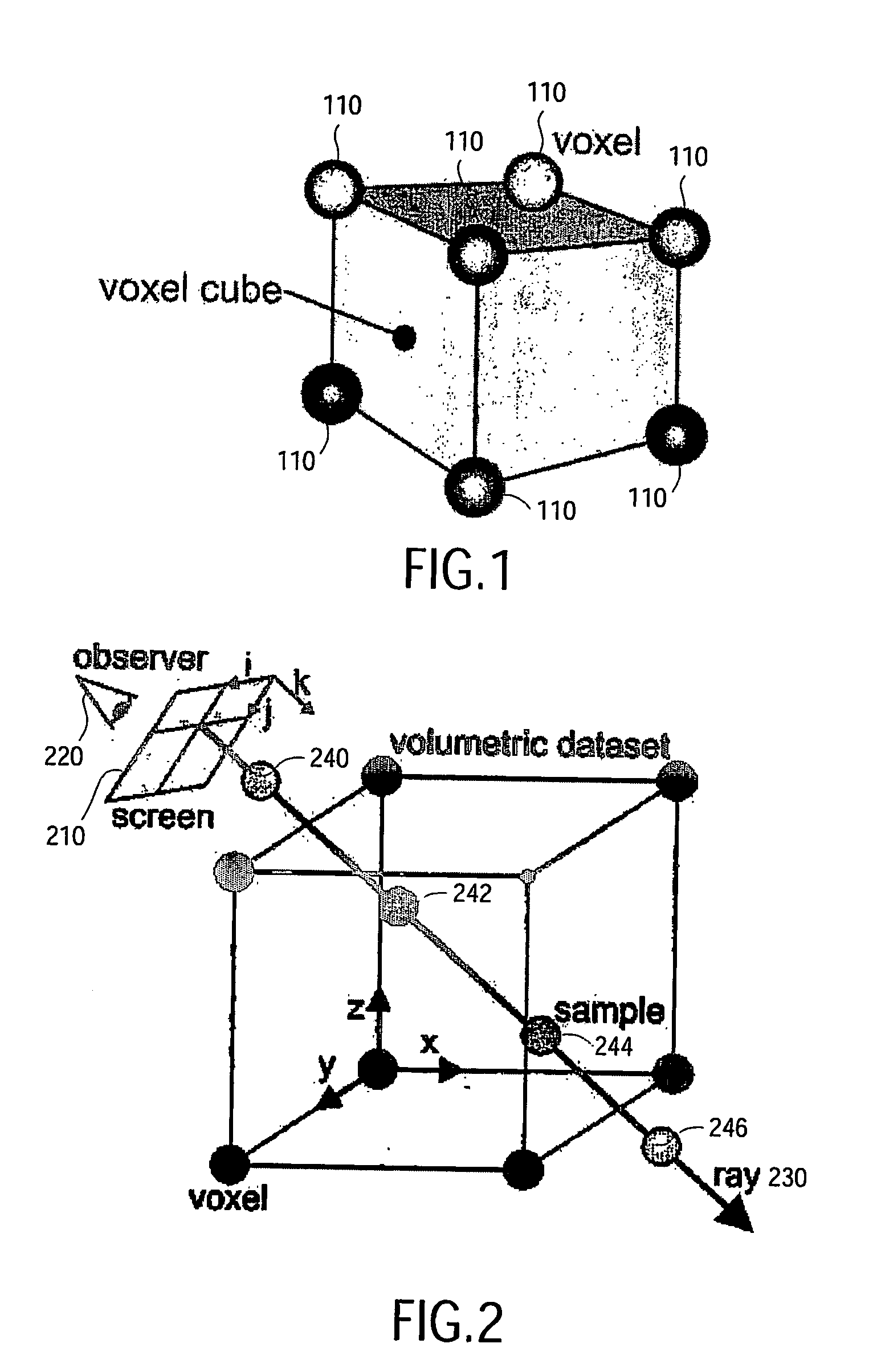
FIELD OF THE INVENTION [0001] The invention relates to a system for visualizing a three-dimensional (hereinafter “3D”) volume, in particular for medical applications. The invention also relates to software for use in such systems. The invention further relates to a method of visualizing a three-dimensional 3D volume. BACKGROUND OF THE INVENTION [0002] With the increasing power of digital processing hardware (in the form of dedicated pre-programmed hardware or a programmable processor) it has become possible to exploit rendering algorithms in actual systems for generating high-quality images from volumetric data sets. For medical applications, the volumetric data sets are typically acquired using 3D scanners, such as CT (Computed Tomography) scanners or MR (Magnetic Resonance) scanners. A volumetric data set consists of a three dimensional set of scalar values. The locations at which these values are given are called voxels, which is an abbreviation for volume element. The value of a...

Claims


Application Information

Patent Timeline
IPC IPC(8): G06T15/20G06T1/60G06T15/00G06T15/08
CPCG06T1/60G06T15/005G06T15/08
Inventor VAN LIERE, FILIPS
Owner KONINKLIJKE PHILIPS ELECTRONICS NV
Learn More