Exposure Apparatus, Manufacturing Method of Optical Element, and Device Manufacturing Method

Inactive Publication Date: 2006-08-03
CANON KK
View PDF4 Cites 38 Cited by
  • Summary
  • Abstract
  • Description
  • Claims
  • Application Information

AI Technical Summary

Benefits of technology

[0010] The present invention is directed to an immersion exposure apparatus that improves the reliab

Problems solved by technology

One major problem in the immersion exposure apparatus is whether the final lens in the projection optical system can endure long-term use.
In addition, there is another problem in which the final lens in the projection optical system contacts the immersion-exposure liquid for a long time period and deteriorates.
However, no protective film has yet been developed which can endure for a long time period under high-intensity ArF excimer laser in the water.
On the other hand, quartz glass has good water resistance but is inferior in transmittance.
Thus, i

Method used


Image

  • Exposure Apparatus, Manufacturing Method of Optical Element, and Device Manufacturing Method
  • Exposure Apparatus, Manufacturing Method of Optical Element, and Device Manufacturing Method
  • Exposure Apparatus, Manufacturing Method of Optical Element, and Device Manufacturing Method

Examples


Embodiment Construction

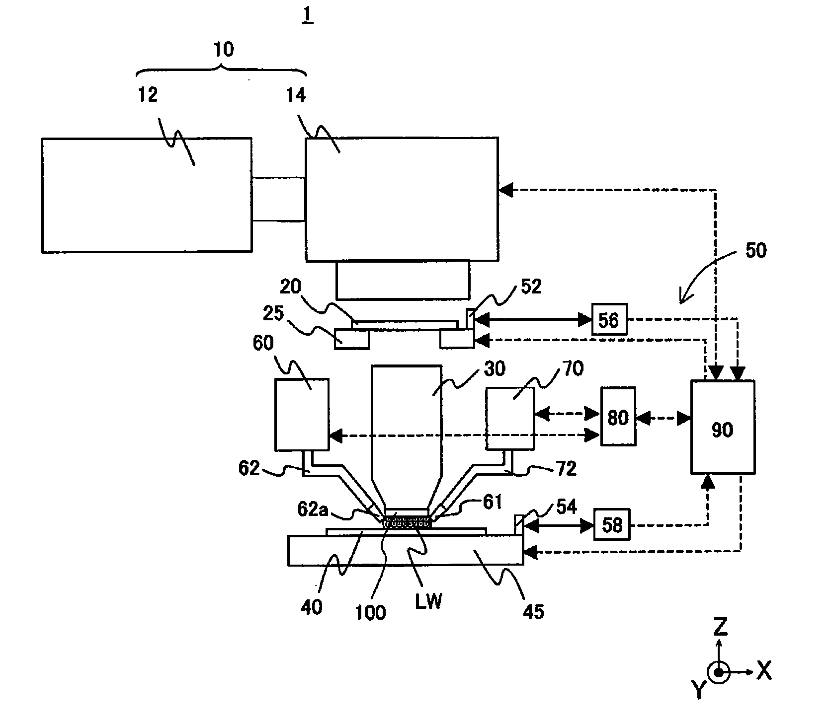
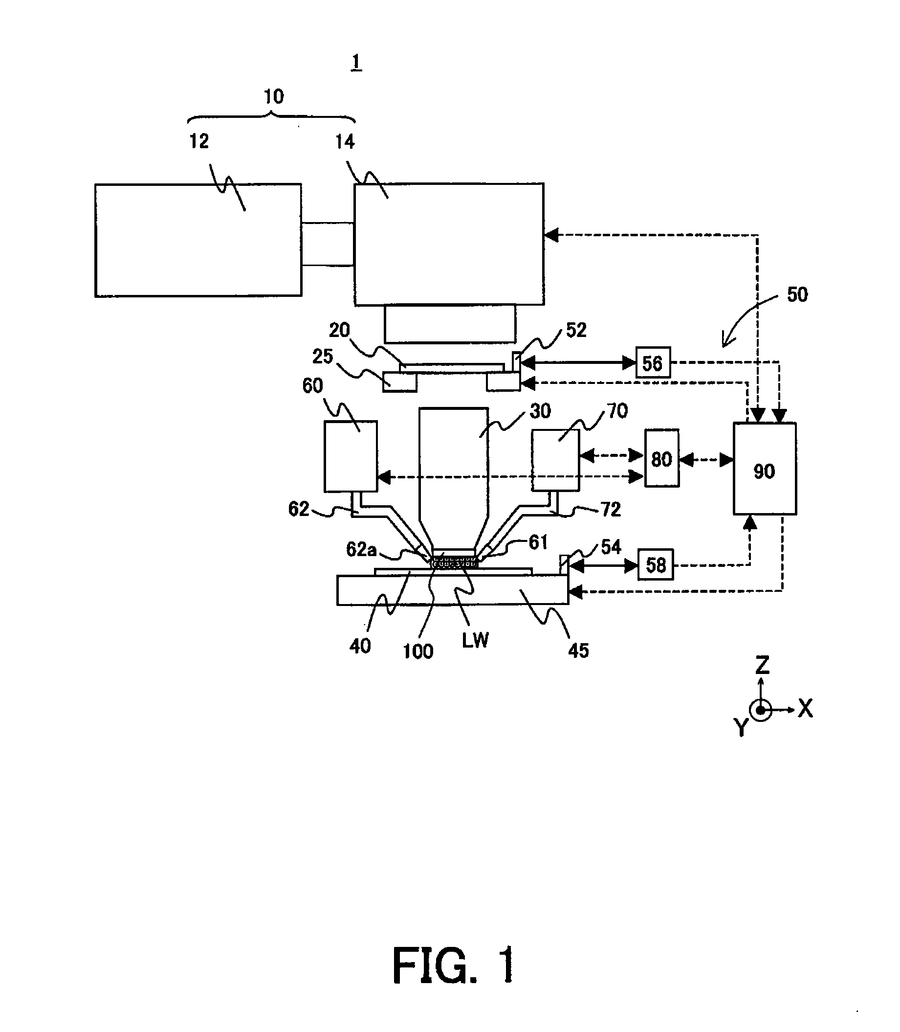
[0021] Referring now to the accompanying drawings, a description will now be given of an exposure apparatus 1 according to one aspect of the present invention. In each figure, like elements are designated by the same reference numerals, and a duplicate description thereof will be omitted. Here, FIG. 1 is a schematic sectional view of the illustrative inventive exposure apparatus 1.

[0022] The exposure apparatus 1 is an immersion projection exposure apparatus that exposes onto a substrate 40 an image of a circuit pattern in a step-and-scan manner, via liquid LW supplied between the substrate 40 and the final optical element (or final lens) 100. The “step-and-scan manner,” as used herein, is an exposure method that exposes a mask pattern onto a wafer by continuously scanning the wafer relative to the mask, and by moving, after a shot of exposure, the wafer stepwise to the next exposure area to be shot.

[0023] The exposure apparatus 1 includes, as shown in FIG. 1, an illumination appar...


PUM


Abstract

An exposure apparatus includes a projection optical system for projecting an image of a pattern of a reticle onto a substrate via liquid, the liquid being filled in a space between an optical element of the projection optical system and the substrate, the optical element being closest to the substrate in the projection optical system, wherein the optical element includes quartz glass that contacts the liquid and is arranged at a side of the substrate, and fluorine-doped quartz glass adhered to the quartz glass.

Description

BACKGROUND OF THE INVENTION [0001] The present invention generally relates to an exposure apparatus, and more particularly to an exposure apparatus used to manufacture various types of devices including semiconductor devices, display devices, detecting devices, imaging devices, and a fine pattern for micromechanics. The present invention is suitable for a so-called immersion exposure apparatus that exposes a substrate via a projection optical system and liquid between the projection optical system and the substrate. [0002] A reduction projection exposure apparatus has conventionally been employed which uses a projection optical system to project a circuit pattern onto a wafer, etc., in manufacturing a semiconductor device or a liquid crystal display device in the photolithography technology. [0003] The minimum critical dimension (“CD”) transferable by the reduction projection exposure apparatus or a resolution is proportionate to a wavelength of the exposure light, and inversely pro...

Claims


Application Information

Patent Timeline
IPC IPC(8): G03B27/42
CPCG03F7/70341G03F7/70958
Inventor HONDA, TOKUYUKI
Owner CANON KK
Why Eureka
Try Eureka