Two mirror re-imaging telescope

a mirror re-imaging and telescope technology, applied in the field of telescope systems, can solve the problems of less physical compactness and weight of two mirror telescopes, poor image quality very stringent volume and weight limitations of space-based applications, and achieve the effects of less physical compactness and weight of two mirror telescopes, poor image quality, and advantageously reduced telescope weigh

Inactive Publication Date: 2006-08-03
THE BOEING CO
View PDF14 Cites 12 Cited by
  • Summary
  • Abstract
  • Description
  • Claims
  • Application Information

AI Technical Summary

Benefits of technology

[0010] An infrared re-imaging telescope is therefore provided that utilizes two mirrors in an off-axis, eccentric-pupil, re-imaging configuration. By only requiring two mirror surfaces, the weight of the telescope is advantageously reduced and the telescope can be more physically compact in com

Problems solved by technology

Space-based applications have very stringent volume and weight limitations.
Three mirror and four mirror telescopes are known to provide good image quality, but are less physically compact and weigh more than two mirror telescopes.
Two mirror telescopes are known to be more physically compact and lighter-weight compared to three and four mirror telescopes, but tw

Method used


Image

  • Two mirror re-imaging telescope
  • Two mirror re-imaging telescope
  • Two mirror re-imaging telescope

Examples


Embodiment Construction

[0021] The present inventions now will be described more fully hereinafter with reference to the accompanying drawings, in which some, but not all embodiments of the inventions are shown. Indeed, these inventions may be embodied in many different forms and should not be construed as limited to the embodiments set forth herein; rather, these embodiments are provided so that this disclosure will satisfy applicable legal requirements. Like numbers refer to like elements throughout.

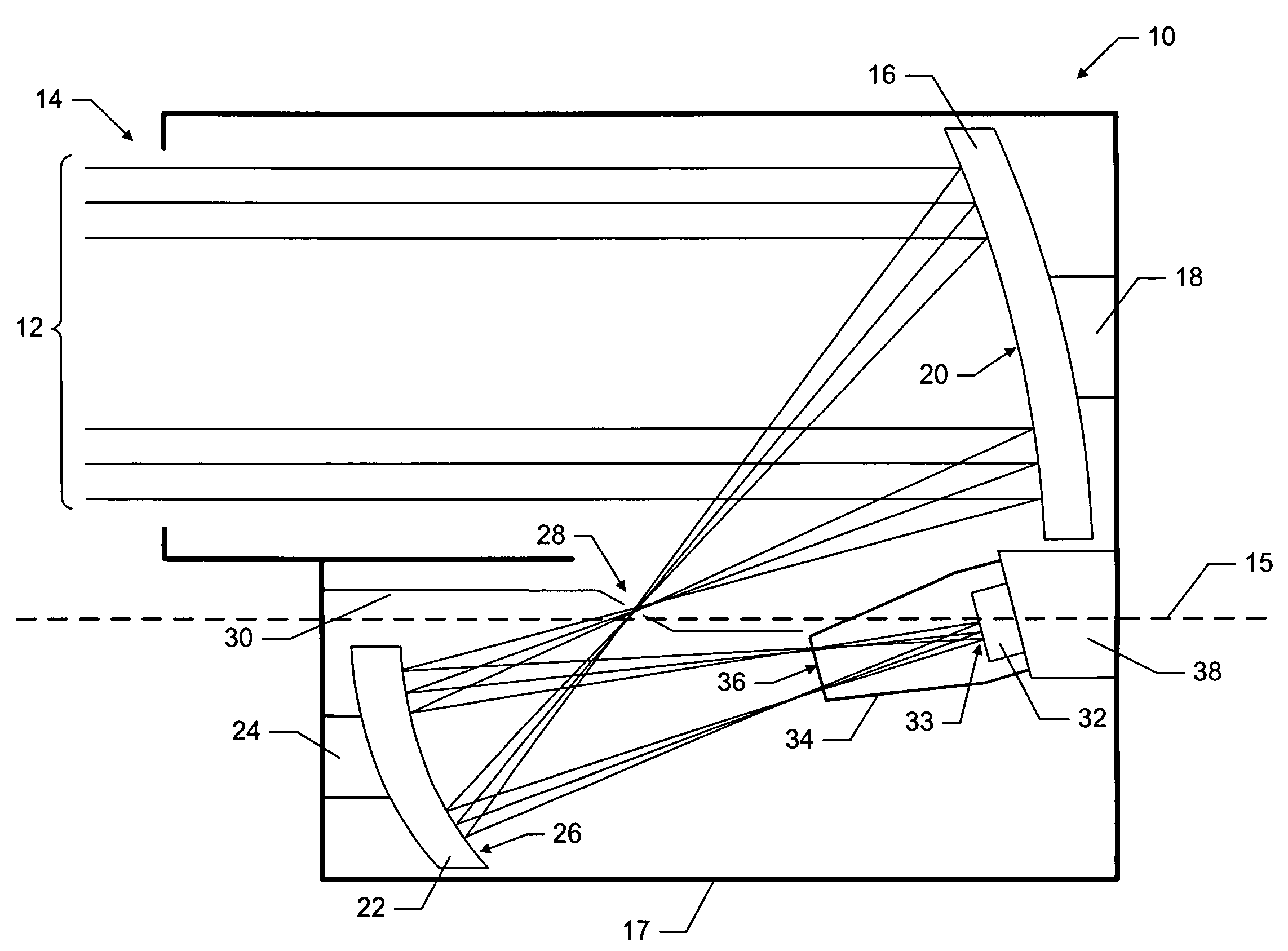
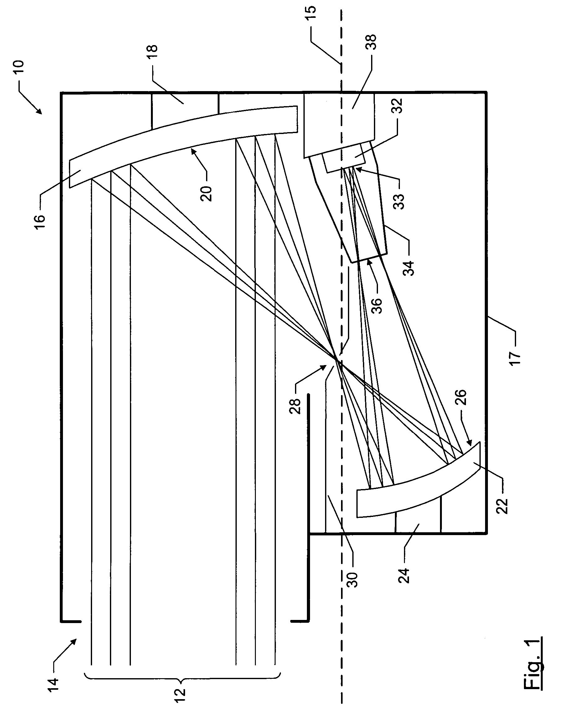
[0022]FIG. 1 is a side elevation schematic of an infrared telescope, in accordance with one embodiment of the present invention. As shown in FIG. 1, infrared light in the form of beam path 12 enters telescope 10 through eccentric pupil 14. As discussed above, pupil 14 is eccentric since the pupil is offset from the optical axis 15, which is shown as a dashed line in FIG. 1. As discussed above, an off-axis telescope views the reflected image on an area of the image plane that is slightly offset from the optic...


PUM


Abstract

An infrared telescope utilizes two mirrors in an off-axis, eccentric-pupil, re-imaging configuration. To improve the image quality of traditional two mirror telescopes, the reflective surfaces of both the primary and secondary mirrors are ellipsoidal. The ellipsoidal surface of the primary mirror has a greater eccentricity than the ellipsoidal surface of the secondary mirror. The infrared light entering through the eccentric pupil strikes the ellipsoidal reflective surface of the primary mirror. The light is reflected from the primary mirror to the ellipsoidal reflective surface of the secondary mirror. An intermediate image of the object being viewed is formed between the primary and secondary mirrors. The light is reflected from the secondary mirror to an image plane. An aperture stop is located between the secondary mirror and the image plane. The image plane is typically located within a cold shield, to reduce the likelihood that stray light will reach the image plane.

Description

FIELD OF THE INVENTION [0001] The present invention relates generally to telescope systems, and more particularly, to two mirror re-imaging telescopes. BACKGROUND OF THE INVENTION [0002] Infrared imaging systems, such as infrared telescopes, are used in many applications where objects that emit infrared energy need to be detected. Infrared energy that is imaged by an infrared imaging system typically has a wavelength from about 1 micrometer to about 26 micrometers. Often these infrared telescopes are used in space-based applications. For example, such a telescope may be used in a global missile defense system to detect missiles for targeting purposes. Such a telescope may also be used in unmanned space vehicles, such as unmanned service vehicles, for locating and identifying objects in space. [0003] Space-based applications have very stringent volume and weight limitations. As such, any systems used in space-based applications must be as physically compact and lightweight as possibl...

Claims


Application Information

Patent Timeline
IPC IPC(8): G02B17/00
CPCG02B17/0615G02B23/06
Inventor LUNDGREN, MARK A.
Owner THE BOEING CO
Why Eureka
Try Eureka