Optical pulse duration extender
a technology of optical pulses and extenders, which is applied in the direction of printers, instruments, active medium materials, etc., can solve the problems of increasing the source power required to accommodate the extenders, reducing the operation cost of the apparatus, and vanishing and useless energy of replica pulses
- Summary
- Abstract
- Description
- Claims
- Application Information
AI Technical Summary
Benefits of technology
Problems solved by technology
Method used
Image
Examples
embodiment 78
[0049]FIG. 10 schematically illustrates a second preferred embodiment 78 of a pulse extender in accordance with the present invention including a delay loop 80. Pulse extender 78 is similar to extender 58 of FIG. 4 with an exception that graded reflectivity beamsplitter 62 of pulse extender 58 is replaced by a graded reflectivity beamsplitter 65 in the form of a meniscus lens having zero dioptric power. Graded reflectivity zones are formed on concave surface 67 of the beamsplitter. Surface 67, considered as a mirror, has the same focal length f as mirrors 64, 66, and 68. Opposing mirrors are spaced by a distance of about 2f such that 1:1 relay imaging conditions are satisfied. Providing that graded reflectivity beamsplitter 65 is a meniscus lens of zero power avoids the beamsplitter changing the divergence of transmitted replica pulses. It should be noted here that the sequence of graded reflectivity zones R1, R2, R3, and R4 (not shown), of beamsplitter 65 must be arranged in the op...
embodiment 86
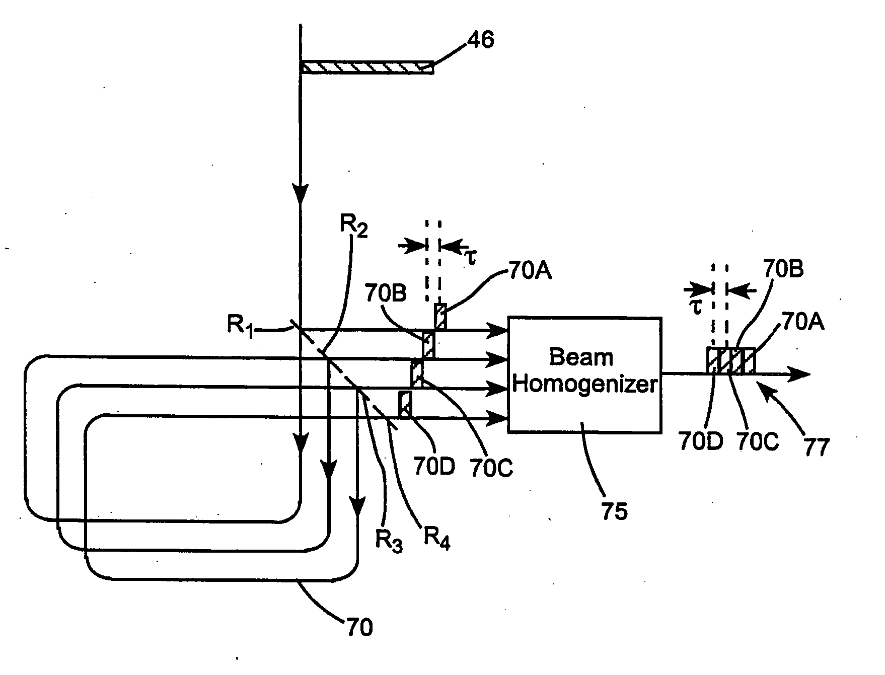
[0050] Referring next to FIG. 11, a third preferred embodiment 86 in accordance with the present invention includes a delay loop 88 formed from a spherical graded reflectivity beamsplitter 65 in the form of a zero power meniscus and having graded reflectivity zones R1, R2, R3, and R4 (not shown) on spherical concave surface 67 thereof, a concave spherical mirror 90, and a plane mirror 92. Surface 67 of graded reflectivity beamsplitter 65 and mirror 90 are arranged confocally. Plane mirror M3 is aligned to cause a circulating beam 70 to make round trips such that the beam is progressively displaced laterally on the beamsplitter surface 67 by the width of the beam, as in other above-described embodiments. Four replica pulses 70A-D are temporally spaced apart by the round trip time of beam 70 in delay loop 88. The zero-power meniscus form of graded reflectivity beamsplitter 65 provides that the divergence of the replica pulses is unchanged. Again, it is preferable that provide a one to...
embodiment 58
[0056]FIG. 13 schematically illustrates, in block diagram form, a preferred arrangement 110 for using the inventive pulse extender in conjunction with an excimer laser 112 and projection optics 114, for example, projection optics of optical lithography apparatus such as a step and repeat projector (stepper) or the like. The arrangement, however, is applicable to any other pulsed laser providing pulses having comparable parameters and to any other optical apparatus. Excimer laser 112, here, provides an input pulse (beam) 46 that is to be broadened by an optical pulse extender in accordance with the present invention. In the arrangement of FIG. 13, the pulse extender is designated as being embodiment 58 of FIG. 3 but could be any other embodiment of the inventive pulse extender. The excimer laser and the extender would usually be assembled as a system as indicated by dashed rectangle 115. The output of the pulse extender, as discussed above, comprises temporally and spatially separate...
PUM
 Abstract
Description
Claims
Application Information
 - R&D
- Intellectual Property
- Life Sciences
- Materials
- Tech Scout
- Unparalleled Data Quality
- Higher Quality Content
- 60% Fewer Hallucinations
Browse by: Latest US Patents, China's latest patents, Technical Efficacy Thesaurus, Application Domain, Technology Topic, Popular Technical Reports.
© 2025 PatSnap. All rights reserved.Legal|Privacy policy|Modern Slavery Act Transparency Statement|Sitemap|About US| Contact US: help@patsnap.com


