
Adaptive multi-level threshold system and method for power converter protection

Active Publication Date: 2006-08-03
ON BRIGHT ELECTRONICS SHANGHAI
View PDF8 Cites 51 Cited by
  • Summary
  • Abstract
  • Description
  • Claims
  • Application Information

AI Technical Summary

Benefits of technology

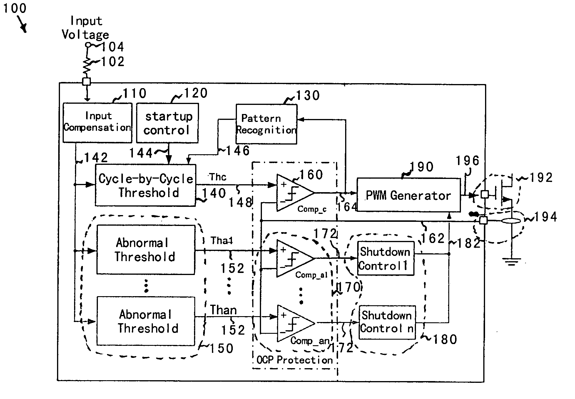
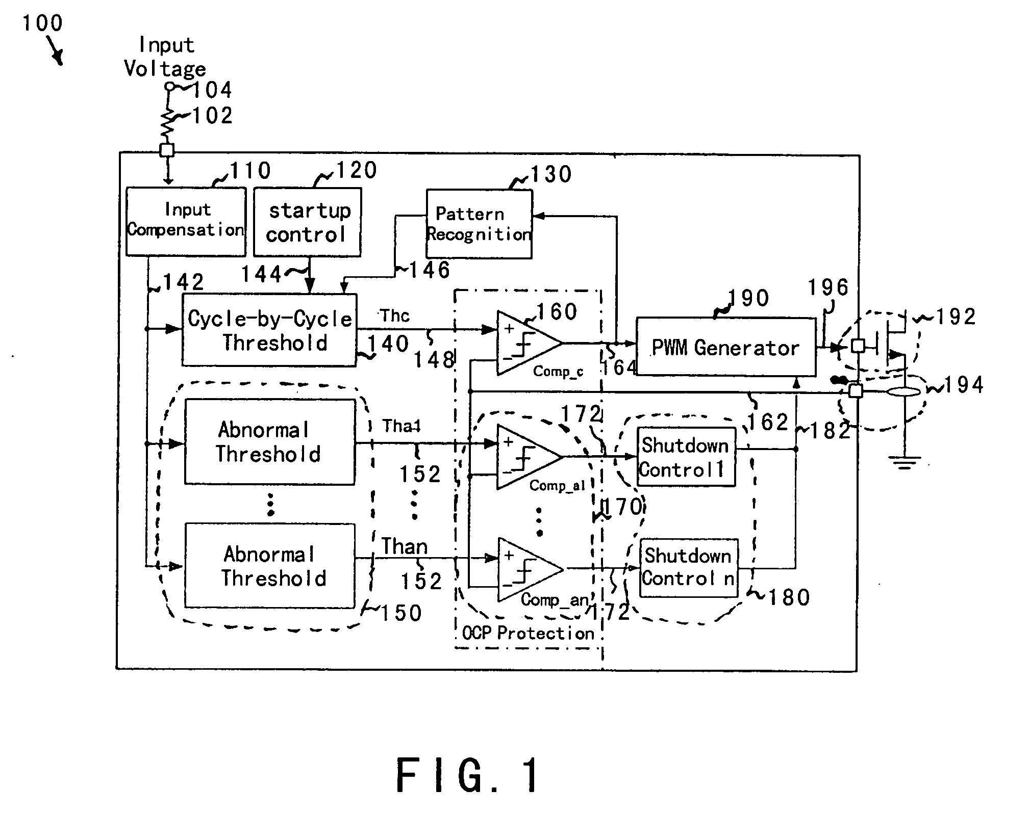
[0018] Certain embodiments of the present invention adjust a cycle-by-cycle threshold in response to a triggering pattern of an over-current protection. The triggering pattern reflects the output loading conditions. For example, if the triggering count is low and random within a given period of time, the output loading condition is usually normal. The cycle-by-cycle threshold for normal operations can be used. In another example, if the triggering count exceeds a predetermined level within a given period of time, the cycle-by-cycle threshold is reduced. In yet another example, the maximum output power is reduced under short-circuit or heavy-overloading conditions until the output loading condition becomes normal. In yet another example, the power converter operates in CCM or DCM. Some embodiments of the present invention adjust a cycle-by-cycle threshold to control the current increase during system startup. For example, during the startup, the cycle-by-cycle threshold is ramped from a low value to the normal value used for normal operations. Certain embodiments of the present invention distinguish the over-current protection for start-up conditions and the over-current protection for normal operations. During the power supply startup, the output voltage of a power converter is usually lower than the output voltage for normal operations. The feedback loop can force the power converter to deliver additional current and thus power to the output. Consequently, the transformer winding current can quickly rise to a very high level. This rapid current rise often causes transient saturation of the winding and damages the converter system due to double magnetic flux effect. According to certain embodiments of the present invention, the over-current threshold is ramped up during start up in order to avoid or reduce the transient saturation and double magnetic flux effect. Hence the system damage can be reduced or prevented.
[0019] Certain embodiments of the present invention provide an abnormal threshold. For example, the abnormal threshold is higher than, equal to, or lower than the cycle-by-cycle threshold. In another example, the abnormal threshold is used for triggering a system shutdown in short-circuit and / or over-loading conditions. Some embodiments of the present invention provide a self recovery mechanism after a predetermined shutdown period. For example, a power converter can operate in the “burst mode” to reduce the output power under abnormally high over-current conditions and recover to normal operations once the abnormally high over-current conditions are cleared. Certain embodiments of the present invention provide an immediate and permanent latch shutdown if the highest over-current threshold is triggered in order to effectively protect the converter system from damage in a timely manner. Some embodiments of the present invention provide a solution for both current limiting and system shutdown. Certain embodiments of the present invention can shorten the OCP de-bouncing and / or delay and overcome the over-current hole problem. Some embodiments of the present invention can improve system flexibility, reliability and safety. Certain embodiments of the present invention can decouple a complicated OCP design into a simple set of protection mechanisms.

Problems solved by technology

But this conventional technique usually cannot adequate protect the power converters under certain operating conditions.

Method used


Image

  • Adaptive multi-level threshold system and method for power converter protection
  • Adaptive multi-level threshold system and method for power converter protection
  • Adaptive multi-level threshold system and method for power converter protection

Examples


Embodiment Construction

[0026] The present invention is directed to integrated circuits. More particularly, the invention provides an adaptive multi-level threshold system and method for over-current protection. Merely by way of example, the invention has been applied to a power converter. But it would be recognized that the invention has a much broader range of applicability.

[0027] The conventional over-current protection (OCP) often fails to limit the current or protect the power converter under various conditions. For example, the power converter is operated in continuous current mode (CCM). If the output is overloaded or short circuited. The current can start off at a value higher than the OCP threshold and thus overstress the power converter. Also, if the power converter experiences inductor saturation for transformer windings, the OCP control can be delayed for such a long period of time that the current may fly off and permanently damage the power converter. As another example, the power converter ...


PUM


Abstract

System and method for protecting a power converter. The system includes a compensation system configured to receive an input signal and generate a control signal, a cycle threshold generator configured to receive the control signal and generate a cycle threshold, and a comparator configured to receive the cycle threshold and a feedback signal and generate a comparison signal. Additionally, the system includes a pulse-width-modulation generator configured to receive the comparison signal and generate a modulation signal in response to the comparison signal, and a switch configured to receive the modulation signal and control an input current for a power converter. The input current is associated with an output power for the power converter. The cycle threshold corresponds to a threshold power level for the output power. The threshold power level is constant, decreases, or increases with respect to the input signal.

Description

[0001] CROSS-REFERENCES TO RELATED APPLICATIONS [0002] This application claims priority to Chinese Patent Application No. (EastIP Ref. No. 05NI1963-1365-SMY), filed Feb. 3, 2005, entitled “Adaptive Multi-Level Threshold System and Method for Power Converter Protection,” by Inventors Zhen Zhu, Jun Ye, Shifeng Zhao, Lieyi Fang, and Zhiliang Chen, commonly assigned, incorporated by reference herein for all purposes. STATEMENT AS TO RIGHTS TO INVENTIONS MADE UNDER FEDERALLY SPONSORED RESEARCH OR DEVELOPMENT [0003] Not Applicable REFERENCE TO A “SEQUENCE LISTING,” A TABLE, OR A COMPUTER PROGRAM LISTING APPENDIX SUBMITTED ON A COMPACT DISK [0004] Not Applicable BACKGROUND OF THE INVENTION [0005] The present invention is directed to integrated circuits. More particularly, the invention provides an adaptive multi-level threshold system and method for over-current protection. Merely by way of example, the invention has been applied to a power converter. But it would be recognized that the in...

Claims


Application Information

Patent Timeline
IPC IPC(8): H02M3/335
CPCH02M1/32H02M3/33507
Inventor ZHU, ZHENYE, JUNZHAO, SHIFENGFANG, LIEYICHEN, ZHILIANG
Owner ON BRIGHT ELECTRONICS SHANGHAI
Learn More