Chucking system for nano-manufacturing

a technology of nano-manufacturing and chucking system, which is applied in the field of nano-fabrication of structures, can solve the problems of minimizing the and achieve the effects of reducing the magnitude of separation force, reducing separation force, and minimizing damage to the recorded layer

Inactive Publication Date: 2006-08-03
CANON KK
View PDF53 Cites 114 Cited by
  • Summary
  • Abstract
  • Description
  • Claims
  • Application Information

AI Technical Summary

Benefits of technology

[0007] The present invention is directed towards a chucking system, including, inter alia, a body having a surface with a pin extending therefrom having a throughway defined therein, and a land surrounding the protrusions defining a channel between the pin and the land. In a further embodiment, the body comprises a plurality of protrusions. The configuration of the chucking system allows varying the chucking force. The present invention is directed towards a method of separating a mold, included in a template, from a solidified layer disposed on a substrate. The me

Problems solved by technology

It is believed that the present chucking system reduces the separation forces requ

Method used


Image

  • Chucking system for nano-manufacturing
  • Chucking system for nano-manufacturing
  • Chucking system for nano-manufacturing

Examples


Embodiment Construction

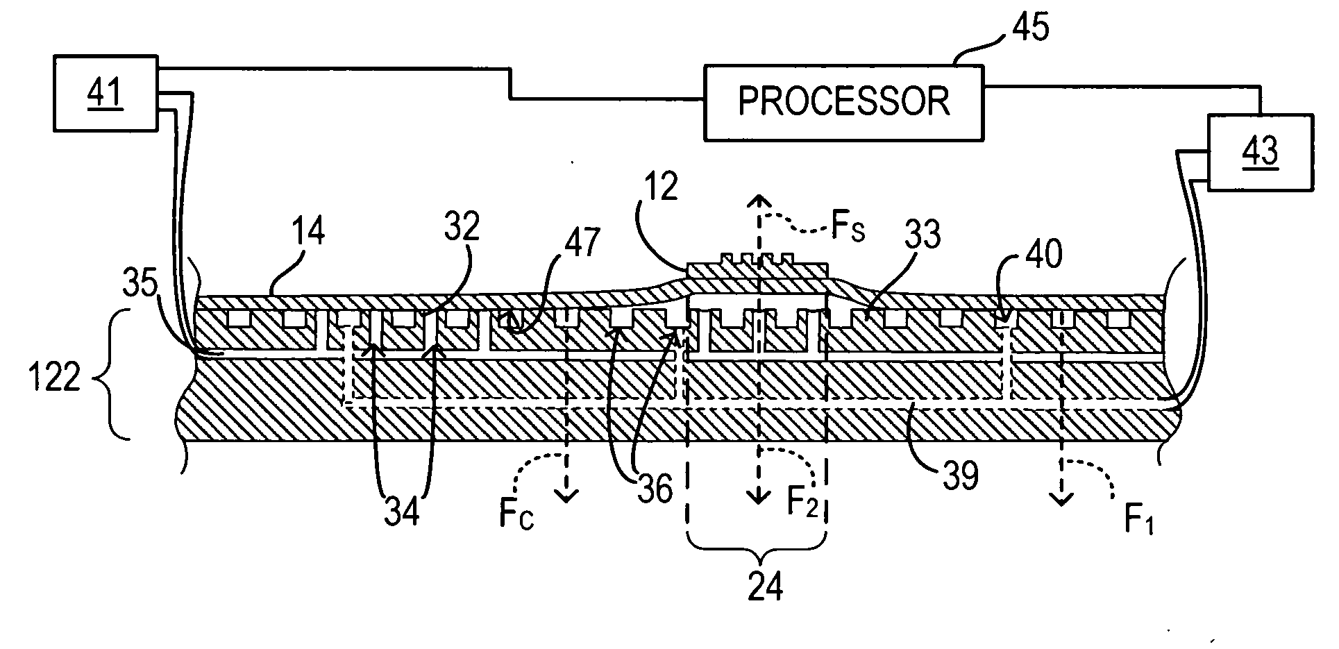
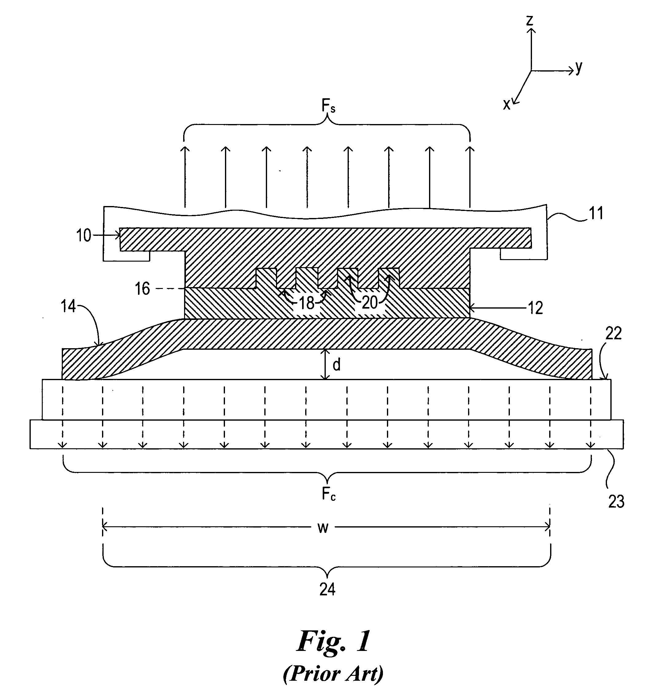
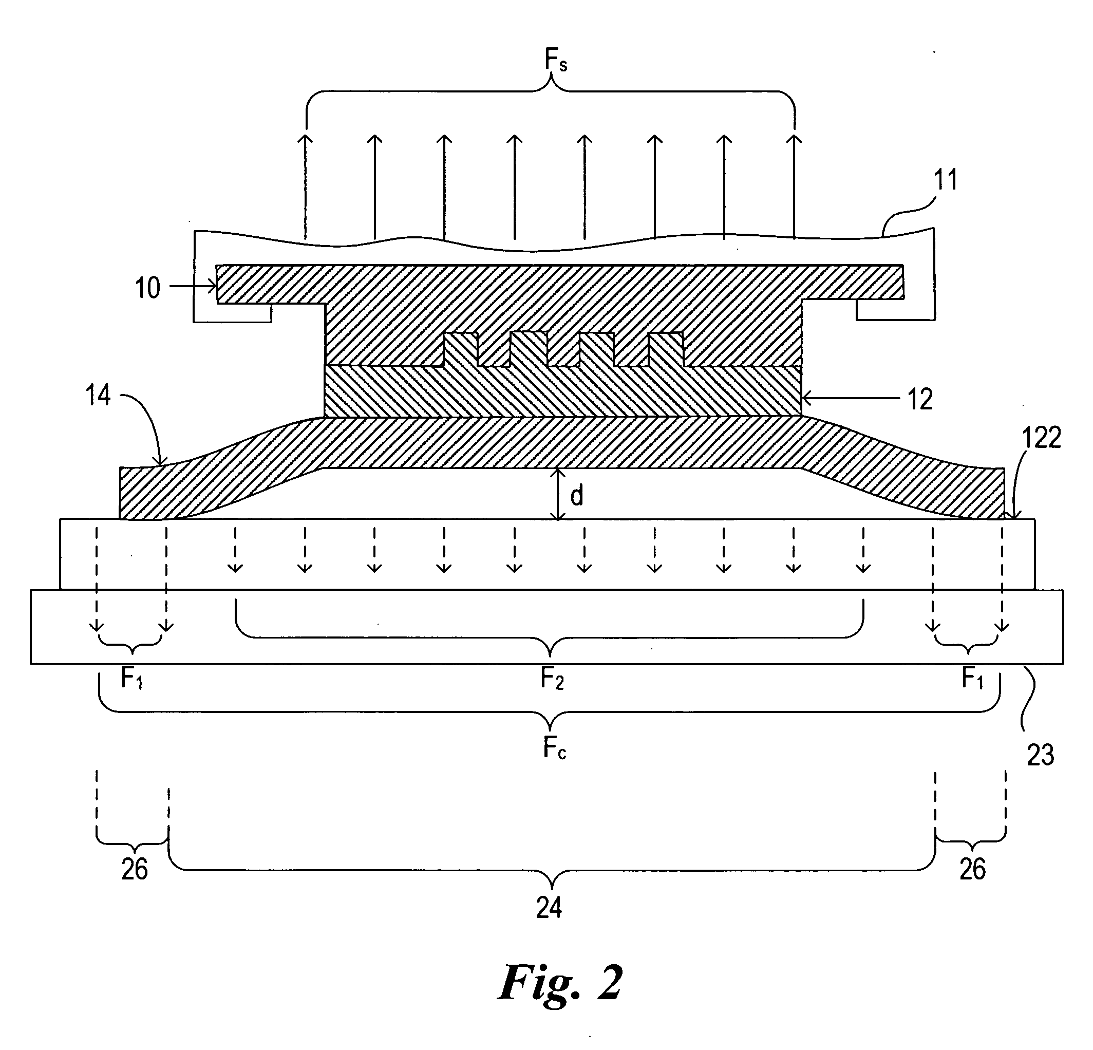
[0027] Referring to FIG. 1, a template 10 is shown in contact with an imprinting layer 12. Typically, template 10 may be comprised of fused silica and imprinting layer 12 may be formed from any material known in the art. Exemplary compositions for imprinting material 12 are disclosed in U.S. patent application Ser. No. 10 / 763,885, filed Jan. 24, 2003, entitled Materials and Methods for Imprint Lithography, which is incorporated by reference. Imprinting layer 12 may be positioned on a substrate 14, with substrate 14 having a thickness ‘t’ associated therewith. Substrate 14 may be formed from virtually any material including silicon, fused silica, metal or compound materials typically associated with the manufacture of integrated circuits. Template 10 comprises a surface 16 having a plurality of features disposed thereon, with the plurality of features comprising a plurality of protrusions 18 and recessions 20. The plurality of protrusions 18 and recessions 20 form a pattern to be tra...


PUM

PropertyMeasurementUnit
Forceaaaaaaaaaa
Pressureaaaaaaaaaa
Shapeaaaaaaaaaa

Abstract

The present invention is directed towards a chucking system, including, inter alia, a body having a surface with a pin extending therefrom having a throughway defined therein, and a land surrounding the protrusions defining a channel between the pin and the land. In a further embodiment, the body comprises a plurality of protrusions.

Description

STATEMENT REGARDING FEDERALLY SPONSORED RESEARCH OR DEVELOPMENT [0001] The U.S. Government has a paid-up license in this invention and the right in limited circumstances to require the patent owner to license others on reasonable terms as provided by the terms of N66001-01-1-8964 and N66001-02-C-8011 awarded by the Defense Advanced Research Projects Agency (DARPA).BACKGROUND OF THE INVENTION [0002] The field of the invention relates generally to nano-fabrication of structures. More particularly, the present invention is directed to a chucking system to facilitate separating a template from a solidified layer disposed on a substrate in an imprint lithography process. [0003] Nano-fabrication involves the fabrication of very small structures, e.g., having features on the order of nano-meters or smaller. One area in which nano-fabrication has had a sizeable impact is in the processing of integrated circuits. As the semiconductor processing industry continues to strive for larger product...

Claims


Application Information

Patent Timeline
IPC IPC(8): B28B11/08
CPCB82Y10/00B82Y40/00G03F7/0002H01L21/6838H01L21/6875Y10S977/887
Inventor BABBS, DANIEL A.CHOI, BYUNG-JINCHERALA, ANSHUMAN
Owner CANON KK
Why Eureka
Try Eureka