Grinding head for a mobile grinding machine and mobile grinding machine comprising such a grinding head

Inactive Publication Date: 2006-08-03
HTC SWEDEN AB
View PDF6 Cites 13 Cited by
  • Summary
  • Abstract
  • Description
  • Claims
  • Application Information

AI Technical Summary

Benefits of technology

[0006] By producing a grinding head with a coupling element in which a plate material is used instead of a fibre reinforced pad or elastomer bush, it will be easily be possible to transfer very high torque. By applying the solution of plates, it is also possible to compensate for relatively large angular deviations in the abraded floor support. By also fitting a compression spring, the necessary compression forces can also be transferred.
[0007] According to a preferred embodiment the coupling element at the drain holes of the plates has spacer elements at least between the plates, which spacer elements are suitably annular metal washers which have a rounded outer edge. The advantage of the spacer element is that by reducing the contact surfaces between the plates, the wear between these is also reduced and hence the flexibility of the coupling element increased. The advantage with the special metal washers is that they eliminate any buckling points for the plates which could o

Problems solved by technology

The cloth however has the limitation that in its thickness direction it can only absorb minimum angular deviations.
Even if absolute flatness is not required on the abraded floor, this disadvantage means that the grinding must largely continue until absolute flatness has been achieved a

Method used


Image

  • Grinding head for a mobile grinding machine and mobile grinding machine comprising such a grinding head
  • Grinding head for a mobile grinding machine and mobile grinding machine comprising such a grinding head
  • Grinding head for a mobile grinding machine and mobile grinding machine comprising such a grinding head

Examples


Example

[0021] On the drawings the same reference numerals are used throughout the various figures to indicate the same parts. For the sake of clarity however not all reference numerals are repeated in all figures and for a complete description of the embodiment shown, all figures should be considered.

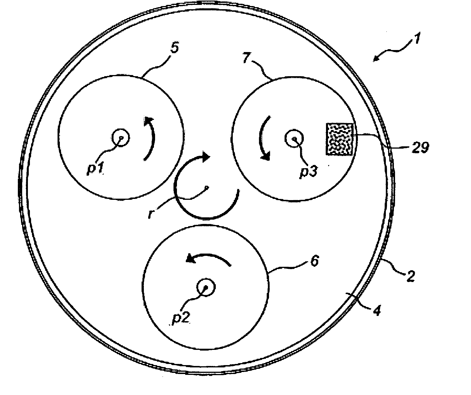
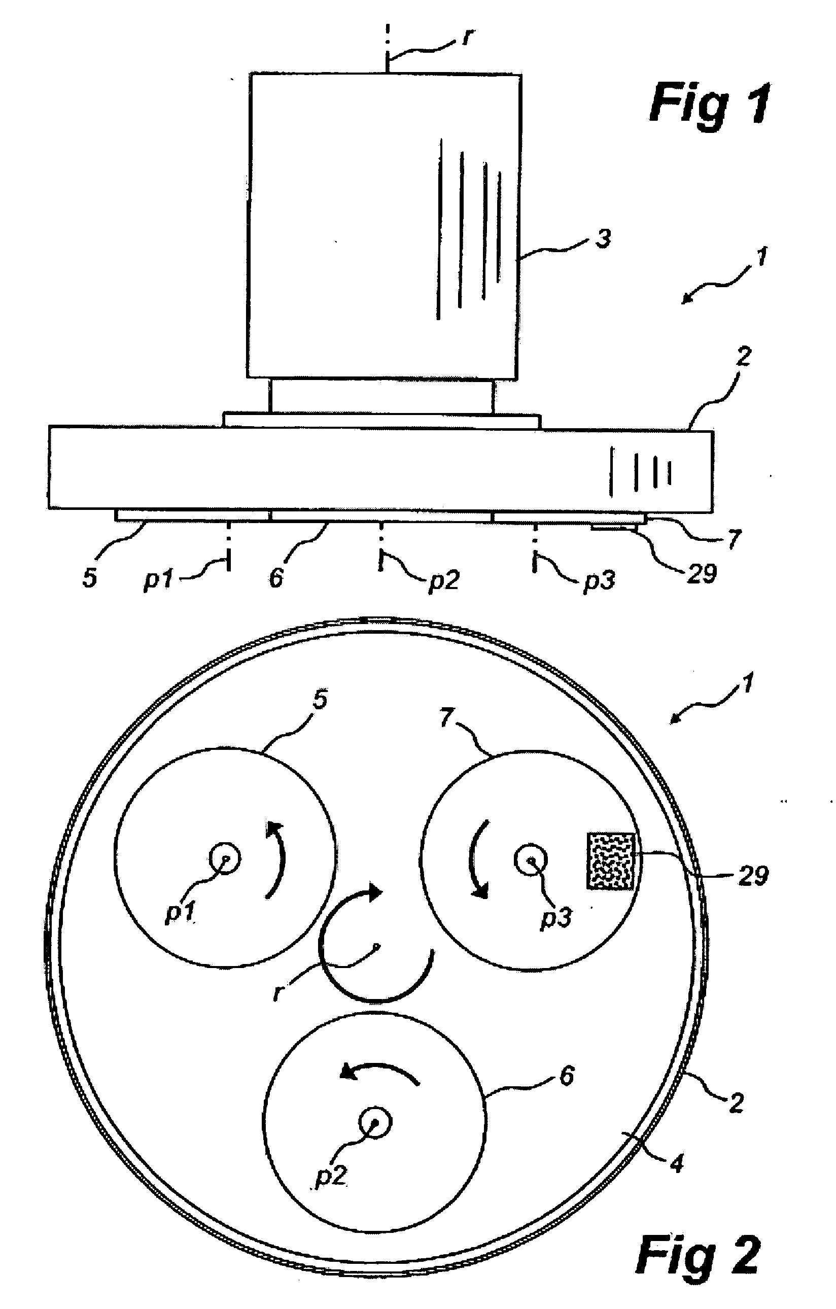
[0022] The preferred embodiment of the grinding head according to the invention is intended for a mobile grinding machine 1 for grinding a stone floor, where this does not exclusively concern a concrete floor. The grinding machine 1 comprises a body 2 to which is coupled a handle arrangement not shown and which carries a drive motor 3, a circular planet disc 4 mounted in the body 2, and three grinding heads 5-7 that are mounted on the planet disc 4 and have an underside intended for mounting of a grinding tool not shown. The planet disc 4 is rotatable by means of the motor 2 in FIG. 2 clockwise around a central, substantially vertical rotation axis r, and the grinding heads 5-7 are rotatable ...


PUM


Abstract

The invention concerns a grinding head for a mobile grinding machine which is suitable for grinding floor surfaces, and a mobile grinding machine comprising such a grinding head. The grinding machine is driven by a motor and has a rotatable planet disc and grinding heads (5-7) rotatable relative to this. The grinding heads (5-7) comprise a carrier (8) which is designed to be rotated by means of the motor, and a grinding disc (9) designed to be driven by the carrier (8) by means of a coupling element (10). The coupling element (10) comprises a multiplicity of plates (11-13) which are stacked on each other, each with a central opening (14) and drain holes (15) distributed around this, and a compression spring (16) which extends through the central opening (14) of the plates (11-13) and by means of screw elements (17) is clamped between the carrier (8) and the grinding disc (9). The screw elements (17) extend through the drain holes (15) of the plates (11-13) and are arranged to connect, alternately in a circular direction around the central opening (14) of the plates (11-13), the carrier (8) with the plate (13) nearest the grinding disc (9) and the grinding disc (9) with the plate (11) nearest the carrier (8). A coupling element is also shown for a mobile grinding machine for grinding a stone floor.

Description

TECHNICAL FIELD [0001] The present invention concerns a grinding head for a mobile grinding machine for grinding stone floors, which machine comprises a body supporting a drive motor, a planet disc mounted on the body and a multiplicity of grinding heads mounted on the planet disc, where the planet wheel is rotatable by means of the motor about a central, substantially vertical rotation axis and the grinding heads in relation to the planet wheel are rotatable about substantially vertical planet axes which are distributed around said rotation axis. PRIOR ART [0002] W094 / 08752 discloses a grinding machine which is intended for precise flat grinding of stone floors, in particular those made of concrete. The grinding machine comprises a multiplicity of grinding heads which each comprise a carrier designed to be rotated by the motor, and each a grinding disc designed to be driven by the carrier by means of a coupling element established between the carrier and the grinding disc. In the k...

Claims


Application Information

Patent Timeline
IPC IPC(8): B24B23/00
CPCB24B7/186B24B41/047
Inventor JEANSSON, STEN
Owner HTC SWEDEN AB
Why Eureka
Try Eureka