

Variable flow device
- Summary
- Abstract
- Description
- Claims
- Application Information
AI Technical Summary
Benefits of technology
Problems solved by technology
Method used
Image

Examples
Embodiment Construction
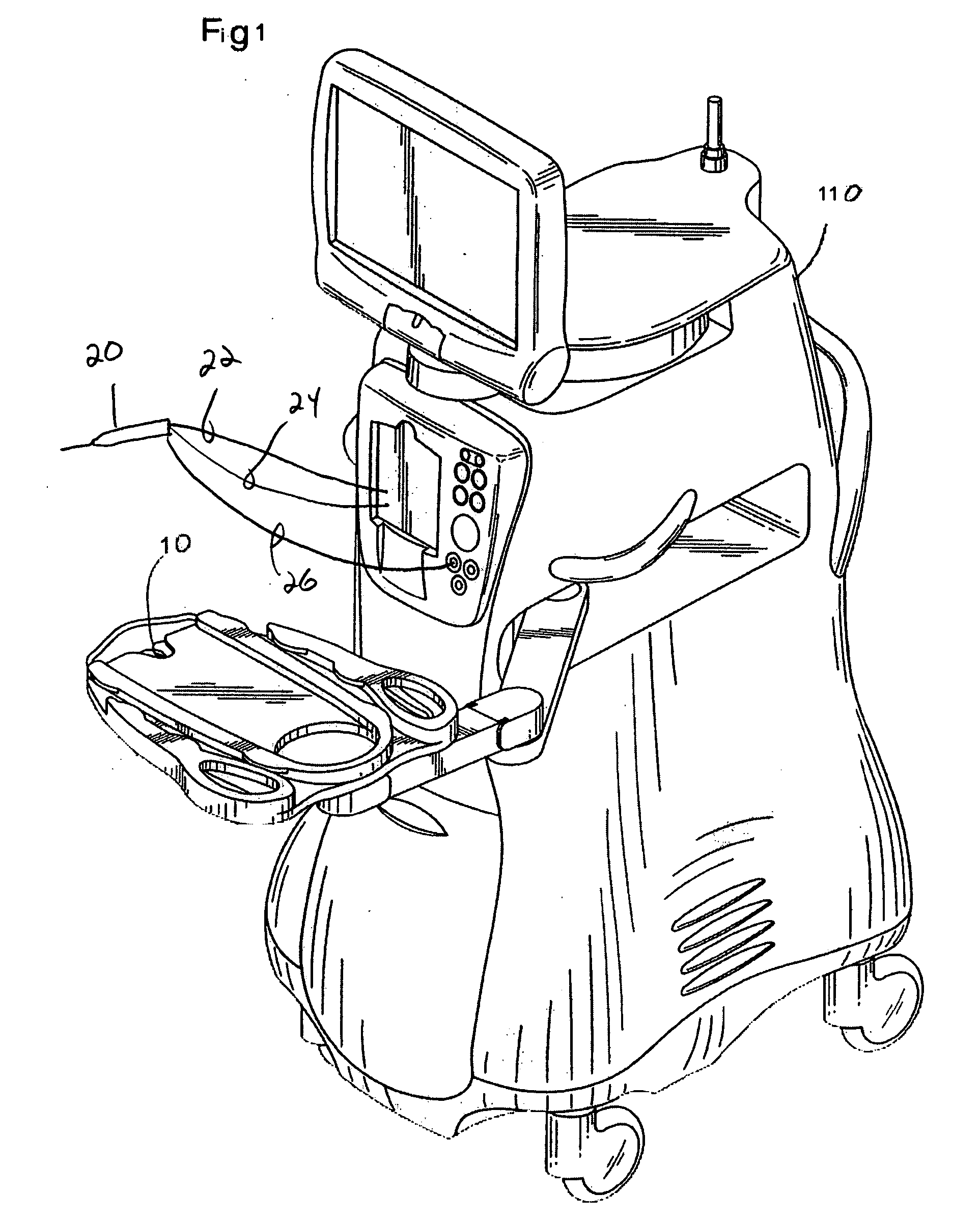
[0022] As best seen in FIG. 1, commercially available surgical systems generally include surgical console 110 having attached, adjustable mayo tray 10 and handpiece 20 attached to console 110 by aspiration tubing 22, irrigation tubing 24 and power cable 26. Power to handpiece 20 as well as the flows of irrigation and aspiration fluid is controlled by console 110, which contains appropriate hardware and software, such as power supplies, pumps, pressure sensors, valves, all of which are well-known in the art.
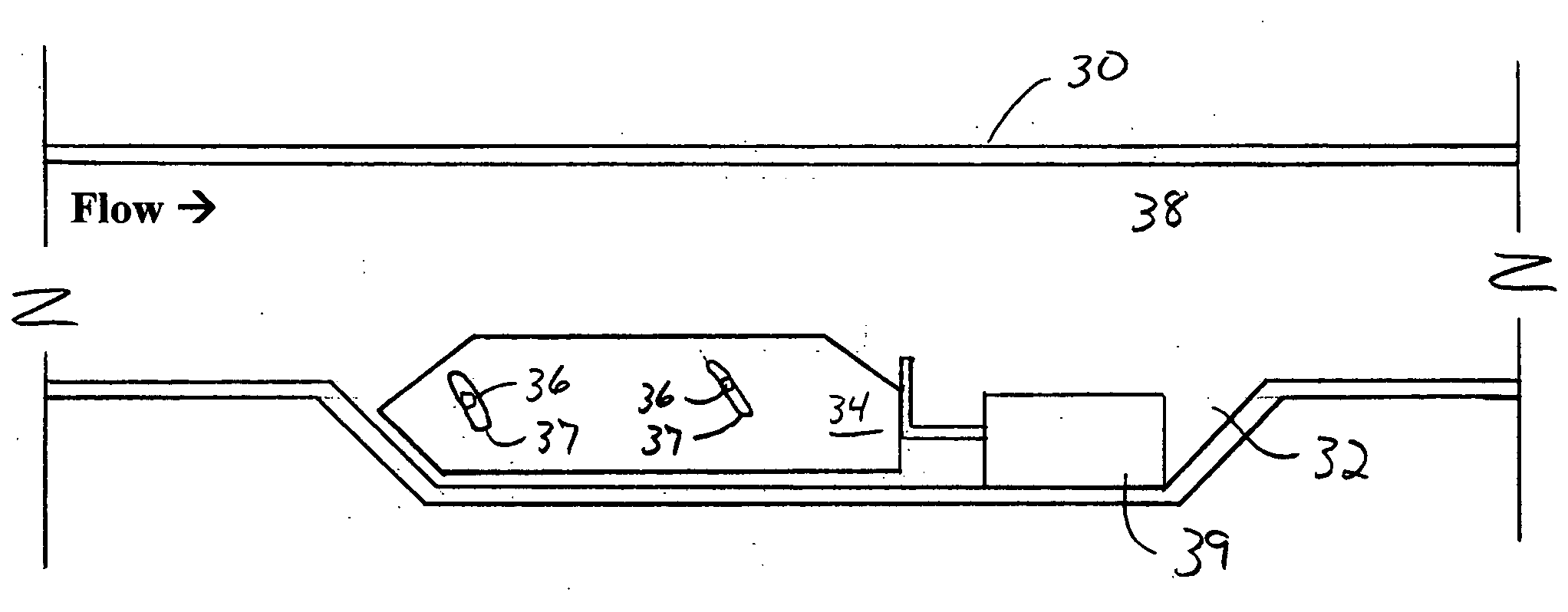
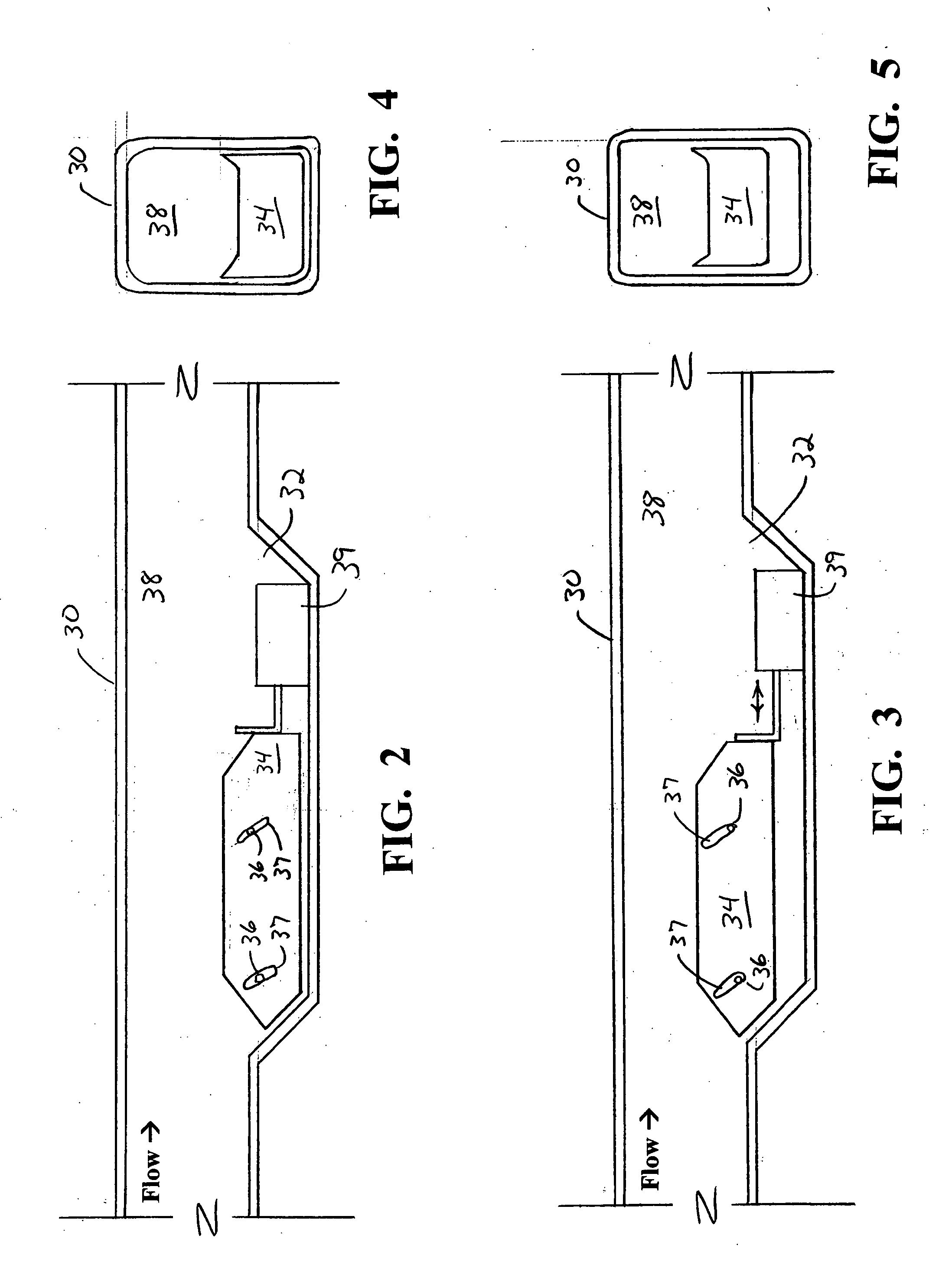
[0023] As best seen in FIGS. 2 and 3, handpiece 30 of the present invention may be of construction similar to that of conventional handpiece 20, except handpiece 30 contains enlarged portion 32 and movable restrictor 34 that is moved within enlarged portion 32 by linear actuator 39, pins 36 and slots 37. As best seen in FIGS. 4 and 5, the shape of restrictor 34 and main flow channel 38 within handpiece 30 is such that regardless of the position of restrictor 34, flow channel 38 r...
PUM
 Abstract
Description
Claims
Application Information