Device for insertion of lacrimal stents

a technology of lacrimal stents and devices, which is applied in the field of lacrimal stents, can solve the problems of eye tearing (epiphora), eye brim with tears continuously, and the canaliculi may become scarred from conjunctival infection, so as to minimize the injury to the lacrimal apparatus and orbit. , the effect of easy insertion

Inactive Publication Date: 2006-08-03
UNIV OF FLORIDA RES FOUNDATION INC
View PDF12 Cites 6 Cited by
  • Summary
  • Abstract
  • Description
  • Claims
  • Application Information

AI Technical Summary

Benefits of technology

[0010] The subject invention is directed to novel system and methods for inserting lacrimal stents. The subject system faciliatates easy insertion of both small and large stents, while minimizing injury to the lacrimal apparatus and orbit.

Problems solved by technology

Quite often a permanent closure occurs in the canaliculi, the lacrimal sac, or the nasolacrimal duct, whereupon the lacrimal fluid no longer can be disposed of in the normal maimer resulting in chronic tearing (epiphora).
In addition, the canaliculi may become scarred from conjunctival infection.
Upon occurrence of blockage in the lacrimal drainage ducts, the eye continuously brims over with tears much to the discomfort, annoyance, and embarrassment of the individual so affected.
A much more serious consequence is the potential for the stagnating tears to result in infection and inflammatory irritation of the mucous membrane with proliferation of the epithelium, hyperemia, and a purulent exudation into the conjunctiva.
On the other hand, the successful cannulation of the punctae with the blunt probes (which are attached to the silastic tubing) can be quite difficult.
As a result of these design requirements, it is difficult for the surgeon to gain the mechanical advantage necessary to successfully caimulate the punctae.
This can lead to frustration for the surgeon, significant operating delays, excessive lid edema, and place the cornea at increased risk of abrasion because of prolonged manipulation.
Older patents discuss ways of using probes to assist guiding the stent into place, but such techniques fall short of addressing the surgical problems and complications.
However, the lack of flexibility of the probe makes it difficult to navigate the angles of the lacrimal apparatus.
Furthermore, the '395 patent could not incorporate larger sized stents since it does not teach a method of implementing a dilation instrument.

Method used


Image

  • Device for insertion of lacrimal stents
  • Device for insertion of lacrimal stents
  • Device for insertion of lacrimal stents

Examples


Embodiment Construction

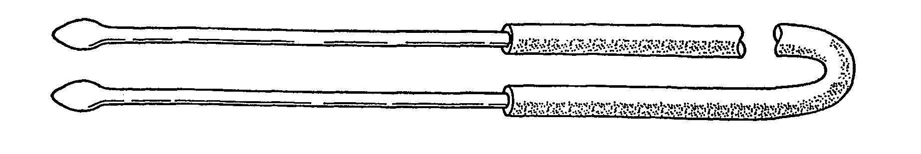
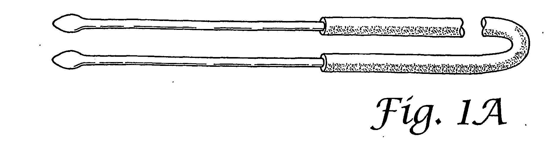
[0022]FIG. 1 shows examples of blunt-tipped flexible probes (FIG. 1A, commonly known as “Crawford Probes”) and rigid tapered dilators (FIGS. 1B and C) that are currently used for inserting lacrimal stents in patients with a need for such stents. The probes and dilators shown in FIG. 1 represent just a few examples of current devices that may be modified according to the teachings herein to achieve probes and dilators for use with the subject methods. See www.fci-opthalmics.com; U.S. Pat. Nos. 5,437,625; 5,318,513; and 6,083,188 for a non-exhaustive sampling of other probes, stents, and related devices that may be modified in accordance with the principles of the subject invention. For example, such devices may include a channel that spans from one end, preferably tip end, of the device to a side port, or through the opposite end, wherein a guidewire may pass through the channel to assist the physician in guiding a stent into the lacrimal apparatus, as taught herein.

[0023]FIG. 2 sho...


PUM


Abstract

Disclosed herein is system for inserting lacrimal stents utilizing a rigid tapered probe and a flexible, blunt-tipped probe, wherein both probes provide a channel for directing a guidewire. The guidewire assists in efficiently positioning lacrimal stents, while minimizing possible injury to the lacrimal apparatus structures.

Description

FIELD OF THE INVENTION [0001] The present invention relates to the field of lacrimal stents, devices for manipulation of such stents, and novel methods in the area of inserting small stents. BACKGROUND OF THE INVENTION [0002] Lacrimal fluid or tears are continuously supplied from the lacrimal gland located laterally and superiorly of the eye through the upper lacrimal duct to the conjunctival sac in which the eyeball is partially encased. Thus, the lacrimal fluid washes across the sclera and other conjunctival components and also the cornea. [0003] The lacrimal apparatus consists of a series of ducts which allow the natural drainage of lubricating tears from the eyes into the nasal cavity. Upper and lower lid punctae, located near the medial aspect of the lids, lead to lacrimal canaliculi. These, in turn, drain to the lacrimal sac, which then becomes confluent with the nasolacrimal duct, the ultimate pathway by which tears reach the nasal cavity. [0004] Quite often a permanent closu...

Claims


Application Information

Patent Timeline
Patent Type & Authority Applications(United States)
IPC IPC(8): A61M29/00A61BA61F9/007A61M25/00
CPCA61F9/00772A61M25/0068A61M25/008
Inventor MELKER, JEREMYS
Owner UNIV OF FLORIDA RES FOUNDATION INC
Why Eureka
Try Eureka